ACAM_64 theory of operation
February 17, 2022An acoustic camera produces an image where the intensity of each pixel represents the amplitude of acoustic waves coming from the corresponding direction. This is akin to an optical camera producing an image where each pixel represents the intensity of light coming from the corresponding direction.
For an optical camera, the lens focuses light coming from a certain direction to the corresponding pixel on the sensor or film. Each pixel in the image represents the intensity of light coming from a specific azimuth (angle in the horizontal plane) and elevation (angle in the vertical plane). The lens does this by slowing and delaying the electromagnetic (light) waves hitting the lens, by precisely the right amount, so that all waves coming from a certain direction arrive in phase in the focal plane, at the position of the corresponding pixel.
An acoustic camera does much the same thing, except that the work of the lens is replaced by a digital computational engine that processes signals captured by an array of microphones (see Figure 1).
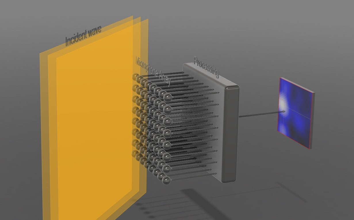 Figure 1. An acoustic camera. Source: Convergence Instruments
An array of microphones captures the sound waves hitting the array from many different directions. For every pixel in the image, a massively parallel digital processing engine applies specific delays, and sums the acoustic signals from every microphone, so that the signals from a specific angle of incidence (azimuth and elevation) arrive in phase. Figure 1 shows that process for a single pixel. Note that a different and precisely adjusted delay (filter) must be applied to every path, from every microphone in the array to every pixel in the image. In the simplest implementation, the intensity of every pixel is calculated as the energy of that sum signal, averaged over a specific length of time.
Frequency, aperture size and image resolution
For an optical camera, as well as for an acoustic camera, the image resolution is proportional to the ratio of aperture size to wavelength.
For an optical camera the aperture size of the camera (the size of the lens or more generally the light collector) is always very large relative to the wavelengths of interest. This is true even for very small lenses, such as those found in camera phones, where the size of the lens is a few millimeters, while the wavelengths of interest are in the hundreds of nanometers (more than 10,000 times smaller). For an optical camera, resolution is rarely limited by the size of the aperture.
For an acoustic camera on the other hand, the frequencies of interest often extend to quite low frequencies (long wavelengths). For instance, the wavelength at 100 Hz is 3.4 m. To have a good resolution at such low frequency would require an array of at least 8 to 10 times as large (25 to 30 m wide). This is usually not practical. Therefore, for acoustic cameras the resolution is typically poor at lower frequencies and improves only as the frequency of interest increases.
Spatial sampling and upper frequency limit
For an acoustic camera, the maximum frequency is limited by the spatial separation between two adjacent microphones. The half wavelength of the maximum frequency sampled by the microphones must be wider than the distance between two microphones. Otherwise, the array is not able to distinguish between sources that are within the field of view, and sources that are outside, leading to artifacts such as phantom images.
For ACAM_64, the distance between microphones is 23 mm, so that frequencies up to 7.5 kHz can be imaged properly. In practice the array is sampled at 16 kHz, with a Nyquist frequency of 8 kHz. The anti-aliasing filters in the camera ensure that the signal energy is low above 7.5 kHz.
Features only possible for an acoustic camera
Because the processing is implemented digitally, a few features are possible that cannot be done in an optical camera:
- The sum signal corresponding to any pixel position is available in the computational engine and can be streamed out, to be listened to. This process is called “beamforming.” The microphone array can be digitally steered to the angle of incidence corresponding to any pixel in the field of view and focus on that source. In addition, it is straightforward to continuously detect the pixel of maximum energy and steer the beamformer to follow that “hot-spot” as it moves across the field of view.
- A filter can be applied to the processing, such that the camera is only sensitive to certain frequencies Furthermore, that filter can be adjusted in real-time, while the images are being captured.
Optical image
Because of the constraint on the aperture, and the range of wavelengths analyzed, an acoustic image is typically low-resolution. Therefore, it is usually difficult to attribute a particular hot zone of the acoustic image to the actual piece of equipment generating the noise.
To aid in the interpretation of the acoustic image, it is very useful to superimpose an optical image of the scene onto the acoustic image.
For ACAM_64, the company developed an Optical Image Kit, which consists of a USB camera, a mount to attach the camera to the top of the microphone array, and software to support the real-time streaming and merging of the optical and acoustic images.
Figure 2 shows a purely acoustic image. Figure 3 shows an acoustic image with the optical image superimposed. It is easier to see where the noise is coming from.
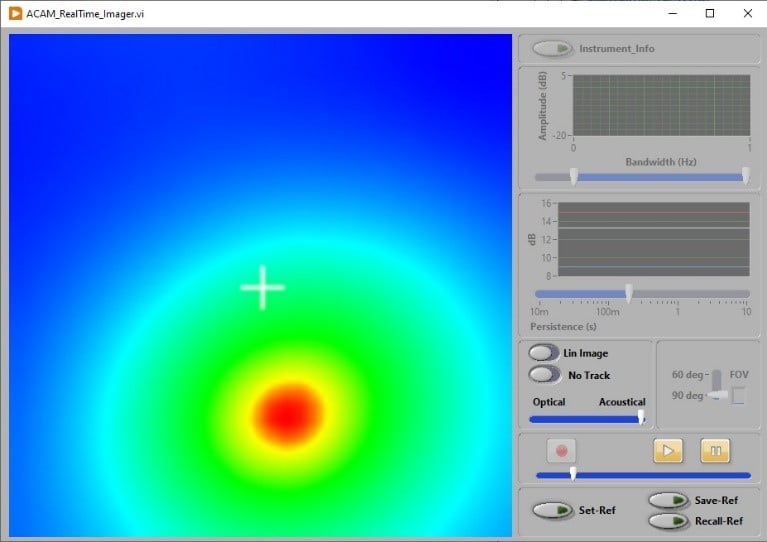 Figure 2. An acoustic image. Source: Convergence Instruments
 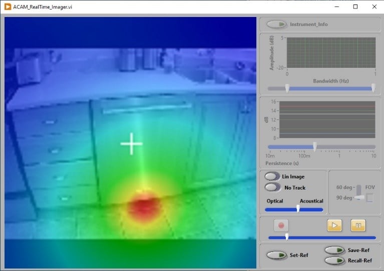 Figure 3. An acoustic image with the optical image superimposed. Source: Convergence Instruments
For more information on ACAM_64, visit Convergence Instruments’ website.