
Hoover Dam completes a pressure-relief valve upgrade
Eric Olson | February 13, 2019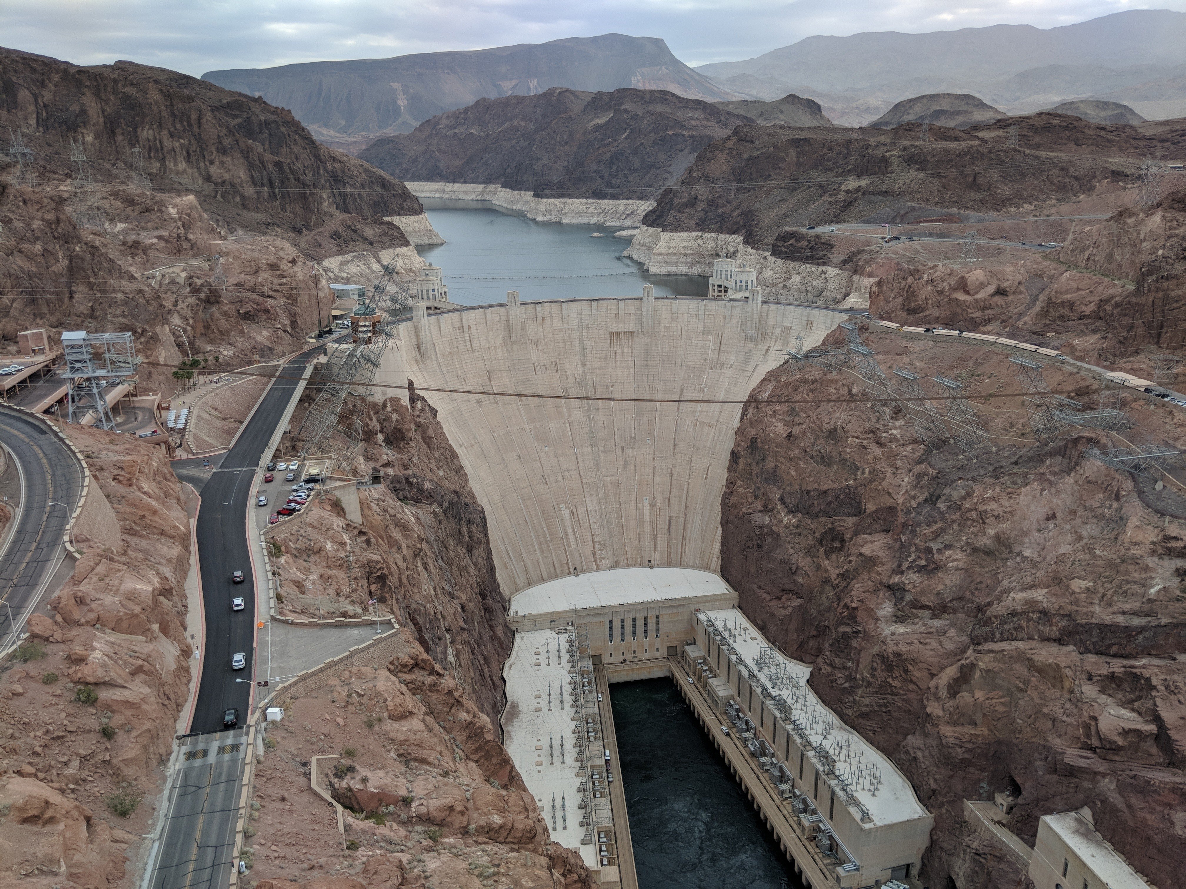 A view of the Hoover Dam from the Mike O'Callaghan–Pat Tillman Memorial Bridge, an arch bridge over the Colorado River completed in October 2010 that was created as a bypass for U.S. Route 93 from its previous path over the dam. Source: Eric Olson
A two-decade-long project to upgrade the Hoover Dam’s original pressure-relief valves (PRVs) is complete.
The last of the 1930s-era PRVs have been replaced with a hydraulically driven solution. The PRVs play a critical role in protecting the dam’s generators and water intake pipes in the event of electrical load issues by bypassing water around the dam’s turbines.
The work completes the latest $6.82 million contract awarded in December 2016 to prime contractor Precision Machine & Supply, Inc. (a division of Andritz Hydro) to replace the three remaining PRVs requiring modernization. Fourteen additional PRVs had already been revamped in years past.
A big dam
Spanning the Colorado River between Nevada and Arizona, the 726 ft tall Hoover Dam opened in 1936. Its 3.25 million cubic yards of concrete hold back the 248 square mile Lake Mead, a reservoir with enough capacity to submerge an area the size of Pennsylvania to a depth of 1 ft.
The Hoover Dam’s 17 turbines have a total rated capacity of nearly 3 million horsepower when operating at their full nameplate capacity of 2,080 megawatts. As recently as 2008, the dam’s average annual power output was more than 4 billion kilowatt-hours, although recently it has operated at closer to a 20% capacity factor due to drought and water management issues in the Southwest.
Hydropower
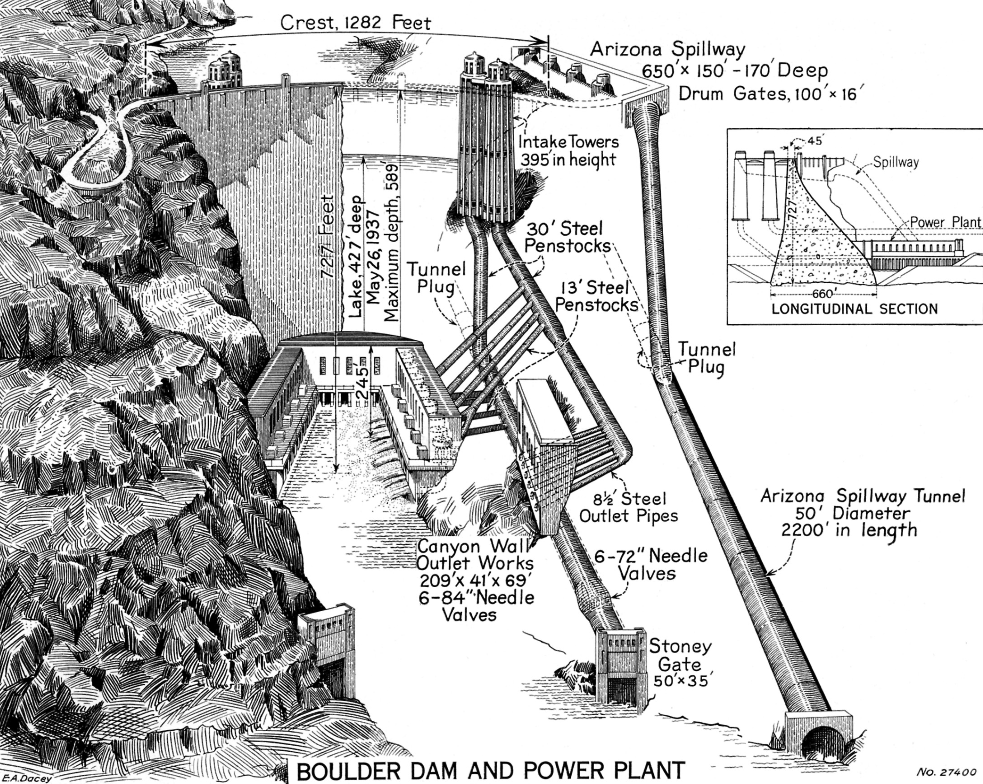 Cutaway view showing the water intake towers and penstocks that feed the Hoover Dam’s turbines on the Arizona side of the dam. A similar arrangement (not shown) is found on the Nevada side. Source: U.S. Bureau of Reclamation. (Click image to enlarge.)
To generate power at the dam, water is directed from Lake Mead to turbine generators at its base. In practice, water from the lake flows into intake towers, where it pours into 30 ft diameter penstock pipes. These pipes channel the water into smaller 13 ft diameter penstocks that increase its pressure to 250 psi. Each penstock leads to a massive, 6 ft tall, three-quarter ton, steel wicket gate.
Passing through the gate, the high-pressure water enters the turbine generator where electricity is generated as the force of the water pushes against the turbine blades, turning the turbine generator’s shaft. The shaft is connected to the generator’s rotor, which, as it spins within a fixed stator, causes electricity to flow due to the motion of magnetic fields past conductors.
This process continues smoothly as long as there is water to flow into the turbines and a destination for all of the electricity generated. Problems arise in the case of a “load rejection” — a situation in which the energy generated by the dam has nowhere to go. This can occur if, for example, transmission lines leading away from the dam are damaged or struck by lightning.
In this case, the turbines must be brought to a stop to avoid damage to the generators that could be caused if they rotate faster than their operating limits — a condition known as overspeed.
Pressure relief
 Compressed gas piston accumulators are installed for the Hoover Dam’s pressure-relief valves. Source: Parker Hannifin
To prevent overspeed, the dam is equipped with PRVs that redirect water away from the turbines in the event of load rejections. The flow, however, cannot be halted too quickly. If it is, a hydraulic shock known as water hammer — caused by the rapid change in momentum — could also damage equipment. To avoid water hammer, the PRVs must open at nearly the same time and at the same rate as the wicket gates slam shut.
The old PRVs, dating to the 1930s, were seen as unreliable in an emergency. They suffered from corrosion damage and used a mechanically actuated design driven by water head pressure.
The new PRVs were designed for fast response times and reliable operation. They are digitally controlled and hydraulically driven with hydraulic cylinders connected to hydraulic power units.
Power is stored for the PRVs in large accumulators. Each PRV is powered by a compressed gas piston accumulator with 180 gallons of oil pressurized to 2,750 psi and two cylinders of nitrogen gas. In total, the 17 accumulators and 34 nitrogen bottles provide on-demand hydraulic power for rapid PRV response time. The PRVs operate within a tenth of a second of the emergency generator shutdown signal.
Mussel trouble
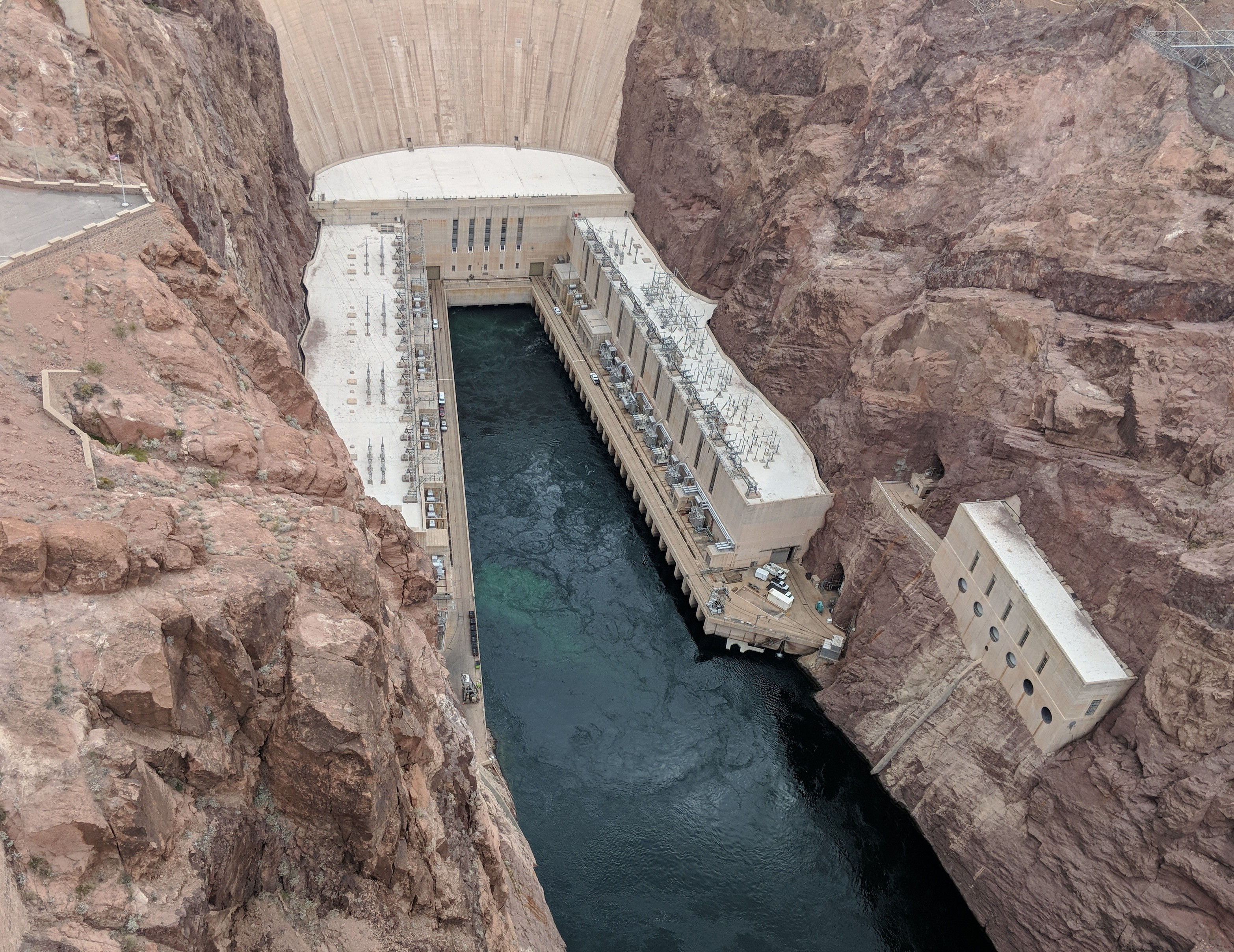 A view of the base of the Hoover Dam from the Mike O'Callaghan–Pat Tillman Memorial Bridge. Source: Eric Olson
The new design has a secondary benefit: combating the quagga mussel. This freshwater mollusk is an invasive species that is native to Ukraine and has infiltrated a number of North American waterways, including Lake Mead. The mussels were jamming the old mechanically actuated PRVs, putting the emergency bypass system at risk of failure. The new hydraulically driven PRVs have enough power to sweep away any quaggas in the way.
The project to replace the dam’s PRVs has been a long process. Refurbishment activities began in 1998. In addition to prime contractor Precision Machine & Supply Inc. (a division of Andritz Hydro), subcontractor Parker Hannifin supplied accumulators and Controlled Motion Solutions Inc. (Comoso) provided engineering support and hydraulic part sourcing.
Now that the project is complete, the dam’s turbine generators are less susceptible to damage in the event of load rejections.
Discover more on Engineering360
Pressure-relief valve products | Learn more about pressure-relief valves
Hydraulic cylinder products | Learn more about hydraulic cylinders
Hydraulic power unit products | Learn more about hydraulic power units
Hydraulic accumulator products | Learn more about hydraulic accumulators



Who provided the digital controls?