The paradigm shift in commercial condensing boilers
January 22, 2021 Figure 1. Firetube condensing boilers are a ubiquitous and perilous default boiler technology. Source: Thermal SolutionsThe vertical firetube boiler is the current standard that is widely used in the industry. However, this design is over 20 years old and contains many design flaws that may have been inadvertently copied by many manufacturers. Newer, high efficiency firetube boilers require frequent maintenance and service due to their higher complexity and use of more moving parts; however, these designs may not include provisions to allow for the cleaning, servicing or repair of these components in the field. Many manufacturers have therefore adopted a mentality similar to that of residential water heaters — if problems arise, it is easier to dispose of the old one and install a new one. This, of course, results in higher maintenance, operating and capital equipment costs.
This article provides a technical overview of the myriad of problems associated with vertical firetube condensing boilers. It further describes the Thermal Solutions Arctic Condensing Boiler, and how it addresses these problems. This effectively shifts the paradigm in the industry from that of “dispose and replace” to that of “maintain and repair,” which leads to higher reliability, greater longevity and lower life-cycle costs — all of which should be expected from a boiler.
Traditional firetube boilers
In traditional horizontal firetube boiler design (Figure 2), a burner heats air in a series of tubes that are submersed in a tank of water. This heat is gradually absorbed into the water as flue gases travel through boiler tubes. When the water reaches a predetermined temperature, it is allowed to flow out of the tank. These models allow for maintenance and access to change out tubes.
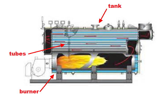 Figure 2. Traditional firetube boiler. Source: Burnham Commercial
In the vertical firetube condensing design (Figure 3), the burner is now located on top of the tank. This move, in order to create a more compact footprint, marks significant change from old reliable and gateway (catalyst) to throw away mentality instilled upon the market by vertical design.
Since most boilers burn hydrocarbon fuels, one of the wasted by-products of combustion is water vapor or steam. A condensing boiler is capable of condensing the water vapor or steam in the otherwise wasted gases in the tubes into liquid water. This phase change process releases additional energy, which is collected and used to further improve the efficiency of the boiler.
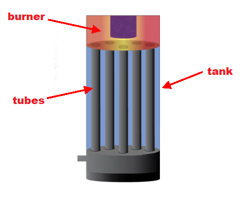 Figure 3. Vertical firetube boiler. Source: Thermal Solutions
Issues above and below the waterline
The vertical firetube boiler design incorporates several potential design issues above and below the waterline, which may result in high stresses, warpage and leakage of the tubes. Furthermore, certain aspects of the design may limit access to important components, making cleaning, servicing and repair of these components almost impossible to perform in the field.
At the top and bottom of the vertical heat exchanger, a tube sheet is used to constrain each of the tubes in the radial direction. The top of the upper tube sheet is above the water line and close to the burner, whereas the lower tube sheet is below the water and further away from the burner. As a result, the temperature of the upper tube sheet is much greater than that of the lower tube sheet. This causes a greater radial thermal expansion of the upper tube sheet with respect to the lower tube sheet, resulting in differential straining between the top and bottom of the tubes. This can cause the tubes to bend, resulting in thermal fatigue of the tubes and their welds. The longevity of this design is questionable at best.
Since the upper tube sheet is in close proximity to the burner, it is exposed to extremely high temperature levels. In fact, the temperature at the center of the tube sheet is much greater than the temperature at the edges, causing diaphragm bending (oil canning) of the tube sheet (Figure 4). This can also cause high bending stresses in the tubes, leading to the potential failure of the tubes and their welds.
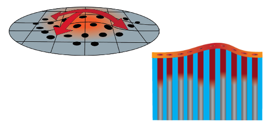 Figure 4. Thermal deformation of the upper tube sheet. Source: Thermal Solutions
Boilers do not operate at full capacity all of the time. In fact, they operate at reduced firing capacity 85% of the time. Under such operating conditions, heat from the burner follows the path of least resistance through the center of the vertical firetube assembly, as opposed to being distributed evenly across all tubes. This creates so-called “zombie zones” that further exacerbate thermal deformation and high stresses in the middle of the firetube assembly (Figure 5).
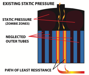 Figure 5. “Zombie zones” in a vertical firetube boiler. Source: Thermal Solutions
The upper tube sheet creates a barrier between the water in the tank and the burner chamber. During operation, bubbles rise to the top of the tank and can be trapped below the upper tube sheet (Figure 6). This condition may occur even in low temperature condensing applications, since this region can still be extremely hot due to its close proximity to the burner. Because the thermal conductivity of air is much lower than that of water, less heat is transferred into the water, reducing the efficiency of the boiler and causing hotspots on the upper tube sheet, resulting in high stresses and warpage.
Many vertical firetube boilers are installed with smaller pumps which reduce size, but can limit flow rate causing greater entrapment of air and sediment. Lower flow rates contribute to impurities collecting in the firetube vessel, creating even more uneven heating and creating thermal stress on the materials.
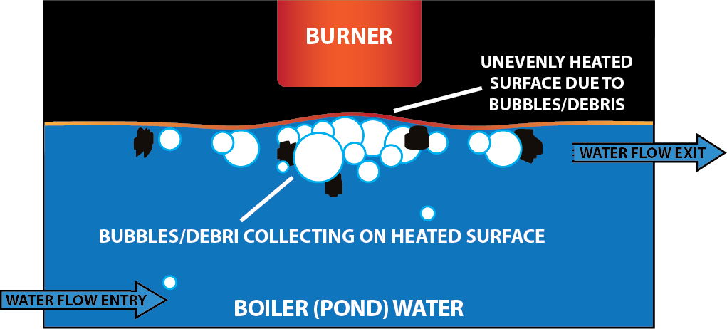 Figure 6. Air entrapment under the upper tube sheet. Source: Thermal Solutions
On the surface, many of the above problems can be serviced, corrected or repaired in the field. However, the basis of the vertical firetube boiler makes this field servicing and repair virtually impossible. Since the burner is located far overhead, it cannot easily be inspected, cleaned or repaired. Furthermore, vertical firetube boilers utilize numerous welds, which create stress concentrations, making them prone to failure. This makes it almost impossible to properly inspect the numerous welds and repair them in the field.
For these reasons, the vertical firetube boiler has served its purpose and it is time to move on. Customer expectations and technology have continued to evolve, whereas the vertical condensing boiler has not, making this design obsolete. An innovative boiler design that addresses the inherent design problems and enables field servicing and repair is clearly needed.
Solutions that drive change
The Thermal Solutions Arctic condensing boiler (1,000 to 6,000 mbh, Amp condensing series 1,000 to 4,000 mbh and Apex condensing series 399 to 800 mbh) addresses numerous problems in vertical firetube condensing boilers that limit longevity, while maintaining low pressure drop, smaller pumps and simplified piping arrangements (Figure 7). The Arctic condensing boiler is designed to reduce thermal stresses that develop during operation by utilizing flexible tubes that are not welded to the upper header. This allows the tubes to expand and contract during normal heating and cooling cycles, reducing thermal stresses. The weld-free seals have a lifetime warranty and have been a proven design for over a century based on the flexible tube design developed by Thermal Solutions’ sister company Bryan Boilers.
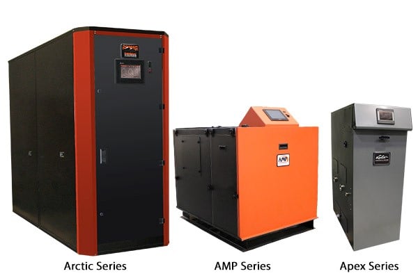 Figure 7. Arctic series (1,000 to 6,000 mbh) and AMP series (1,000 to 4,000 mbh) boilers. Source: Thermal Solutions
Additional design advantages have been implemented in the Arctic and AMP condensing boilers to improve heat transfer from the burner and reduce thermal stresses plaguing vertical condensing designs. Heat transfer from the burner to the tubes is a function of the material’s thermal conductivity, the temperature differential between the water and the burner, the thickness of the tube material and the surface area. The Arctic condensing boiler substantially increases the effective surface area between the boiler and tubes, which increases heat transfer and enables lower operating temperatures (which may increase thermal stress). The boiler does not use tube sheets, which eliminate differential straining and warpage that may be transferred to the tubes. Although the boiler uses similar sized pumps as the traditional vertical firetube boiler, the use of larger diameter tubes enables higher flow rates, which minimize air and sediment entrapment and ultimately create uniform and stable heat zones.
In regard to serviceability, it is the only field-serviceable condensing boiler design in the industry. Vertical firetube boilers place the burner on top, which is difficult to reach and inspect. On all the Arctic and AMP series boilers, the burner is located up front, and can be easily set-up, inspected and serviced. Removable panels around the boiler facilitate access to the burner chamber and entire heat exchanger, enabling burner maintenance without disconnecting any blowers or gas piping. The boilers can therefore be cleaned periodically to ensure maximum efficiency throughout its use.
This creates a new-age boiler solution that does not suffer the setbacks of vertical condensing designs. Arctic designs are field serviceable and easily repaired or cleaned. There are no operational issues with air entrapment or burner stagnation. And the more even heating cycles decreases thermal stress on materials and components, ultimately creating a more reliable and efficient heating technology.
Conclusion
Engineers and facility managers want more from condensing boilers and are learning about and recognizing the benefits of the Arctic condensing boiler. It is a less expensive and more reliable piece of equipment to own and operate, and it readily adapts to new construction and retrofit installations. It brings the “boiler” back to condensing.
Thermal Solutions LLC, of Lancaster, Pennsylvania, is a designer and manufacturer of ultra-high efficiency thermal heating equipment and systems for hot water systems, including boilers, water heaters, heat exchangers, storage tanks or skids, control systems and accessories. Thermal Solutions serves industrial, commercial and institutional heating and domestic hot water applications. Their products are designed and manufactured in the United States and certified to stringent design standards, such as UL®, cUL®, ETL and ASME.
Learn more at the Thermal Solutions webpage.


