How does a pressure-compensated flow control valve work?
Eric Olson | October 09, 2019Pressure-compensated flow control valves are designed to provide a constant volume flow rate independent of the pressure drop across the valve. By contrast, non-pressure-compensated valves have a variable flow rate that changes if the pressure drop across the valve fluctuates.
Applications
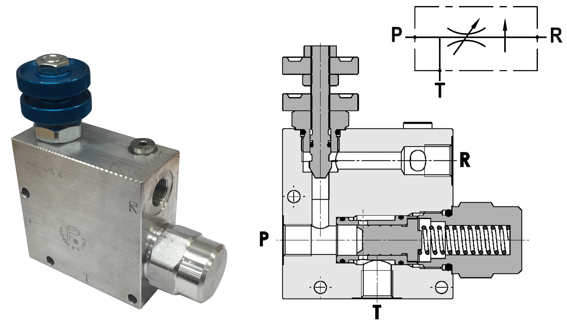
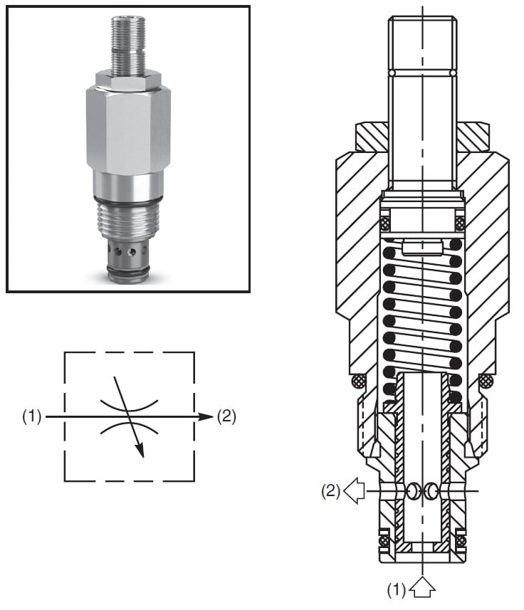 In-line pressure-compensated flow control valve. Source: Parker Hannifin (Click image to enlarge)
Pressure-compensated flow control valves are useful in a variety of hydraulic applications. For example, they benefit situations where it is necessary to maintain a constant speed of operation of a hydraulic cylinder regardless of the magnitude of the load that the cylinder is moving. This is because the speed of a hydraulic cylinder is proportional to the volume flow rate of hydraulic fluid it receives.
Flow rate delivered by a non-pressure-compensated flow control valve will fluctuate if the load on the cylinder changes. A heavy load on the cylinder will increase the pressure at the outlet of the valve ahead of the cylinder compared to a lighter load. The change in pressure drop across the valve alters the flow rate it delivers to the cylinder. Pressure-compensated flow control valves automatically adjust to such changes in pressure drop to deliver a constant flow rate that will provide smooth, constant-speed motion of the hydraulic cylinder.
Pressure-compensated flow control valves are also useful in maintaining constant rpm of a hydraulic motor independent of load on the motor. Much like the example above, changing loads on the motor will result in a fluctuating pressure drop across the valve ahead of the motor. Pressure-compensated flow control valves compensate for these fluctuations to provide a steady flow rate to the hydraulic motor, maintaining its rpm at a constant rate.
Pressure-compensated flow control valves can compensate for pressure fluctuations on either the supply side (inlet) or the load side (outlet) of the valve.
Principle of operation
A pressure-compensated flow control valve typically consists of a variable orifice and a pressure compensator within a single valve body.
The overall path that fluid takes through the pressure-compensated valve is from the supply through the inlet and compensator orifice, around the compensator spool, through the variable orifice and out the outlet.
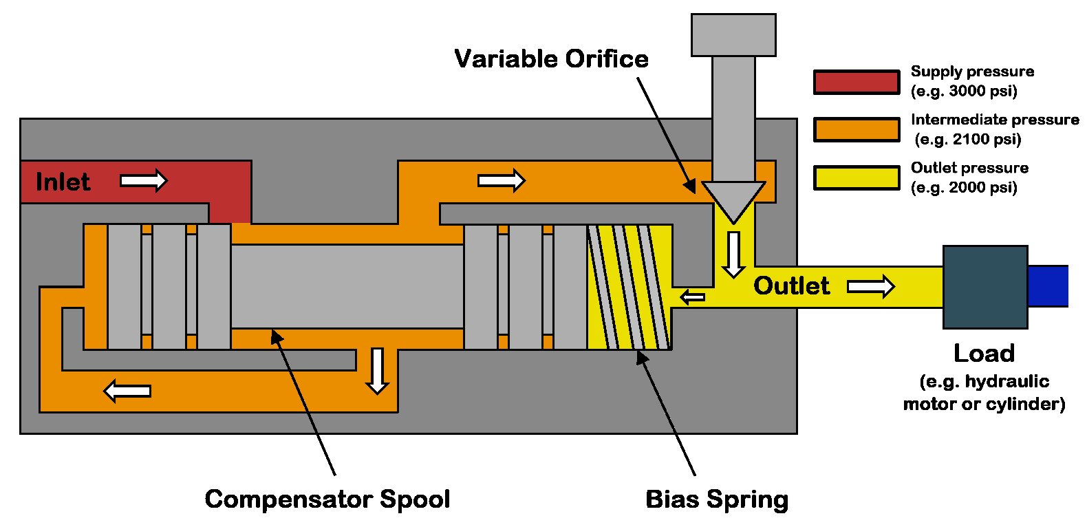 Simplified diagram illustrating the components, fluid flow path and fluid pressures within a pressure-compensated flow control valve. (Click image to enlarge)
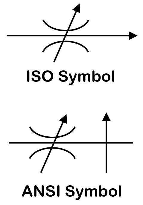 ISO and ANSI schematic symbols for pressure-compensated flow control valves.
The desired flow rate is set on the variable orifice by adjusting the pass-through area of the orifice. This adjustment can be made manually by means of a knob, screw or lever on the valve or remotely with electronic signals to a solenoid actuator attached to the variable orifice. The pressure compensator automatically adjusts the size of the orifice between the inlet flow and compensator spool, modulating the flow of fluid that enters the valve to maintain a constant pressure drop across the variable orifice, providing a constant flow rate through the valve.
The variable orifice consists of a valve stem with a pointed end that moves toward and away from a seat to adjust the size of the opening through which fluid can pass. When the stem tip is in full contact with the seat, the orifice is closed and no fluid can pass. As the stem tip is moved away from the seat, the orifice opening is made progressively larger, allowing more fluid to pass.
The pressure compensator consists of a spool valve anchored by a spring. The compensator spool is comprised of a plunger that slides in a cylindrical barrel. The plunger has thin and wide sections along its length. The wide sections, known as lands, match the diameter of the barrel and block fluid flow if the plunger is positioned so that the lands are adjacent to the ports. The narrow, waisted sections allow fluid to pass through the spool.
 Flow-rate is adjustable by turning the knob on top of this three-way pressure-compensated regulator manufactured by Fluid-Press. Source: Berendsen Fluid Power (Click image to enlarge)
The spool is anchored at one end to the valve housing by a spring, which applies a force to that end of the spool. Fluid from past the variable orifice near the valve’s outlet is ported to the anchored end of the spool to apply an additional force corresponding to the load pressure. The load pressure is the pressure in the line leading from the pressure-compensated flow control valve to the load, such as a hydraulic motor or cylinder.
Fluid that has passed the inlet and compensator orifice but has not yet reached the variable orifice is ported to the other end of the spool (the far end opposite the end attached to the spring). The fluid at this end applies a force to the spool that opposes the force on the spool from the load pressure plus the spring pressure. These opposing forces cause the spool to move in the barrel, modulating the size of the opening of the orifice through which fluid flows from the flow supply until the forces on either end of the spool are balanced.
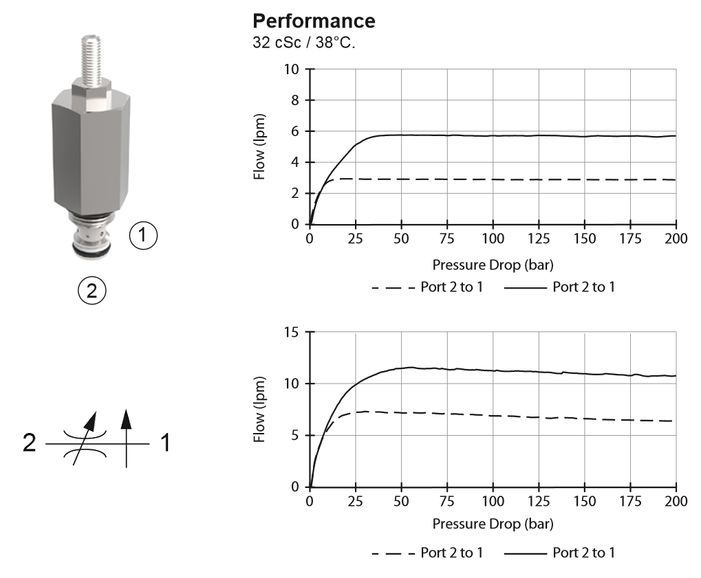 This pressure-compensated adjustable flow control valve maintains a constant flow rate out of port 1 regardless of load pressure changes in the circuit downstream of port 1, as shown by the performance graphs plotting pressure drop from port 2 to port 1 across the valve versus flow rate through the valve. Flow rate is adjustable by turning a knob attached to the threaded portion at the top of the cartridge. Source: Related Fluid Power (Click image to enlarge)
Thus, fluid flows from the supply, around the compensator spool and through the variable orifice, while the pressure drop across the variable orifice is kept constant, enabling the valve to output a constant flow rate independent of a changing pressure drop between flow supply and load on either end of the pressure-compensated valve.
Flow rate is also affected by the viscosity of the fluid, which varies with fluid temperature. Some pressure-compensated flow control valves are equipped with a temperature-sensitive element that adjusts the position of the pressure compensator in response to temperature variations to maintain a constant flow rate independent of changing fluid temperature and viscosity. Some designs also attempt to minimize flow rate variations due to changing viscosity with a sharp-edged orifice design for the variable orifice.
Conclusion
The pressure compensator is the key element of the pressure-compensated flow control valve. Without it, the flow rate exiting the valve would vary as pressure across the valve changed. A higher pressure drop would result in a higher flow rate as more fluid is forced through the valve; a lower pressure drop would result in a lower flow rate.
The pressure compensator maintains a constant internal pressure drop across the variable orifice by automatically adjusting volume flow rate delivered to the variable orifice from the flow supply in response to changing pressure drop between the inlet and outlet of the valve. The constant internal pressure drop across the variable orifice produces a constant volume flow rate out of the valve regardless of changes in pressure between the valve inlet and outlet.
Discover products on Engineering360