How does a pressure-compensated electric motor-driven axial piston hydraulic pump work?
Eric Olson | October 15, 2019Hydraulic pumps generate pressurized hydraulic fluid to power hydraulic components. Electric motor-driven hydraulic pumps convert electrical energy to hydraulic power. The electric motor, powered by an AC or DC current, spins a drive shaft. The drive shaft is coupled to the hydraulic pump which converts low-pressure fluid to high-pressure fluid.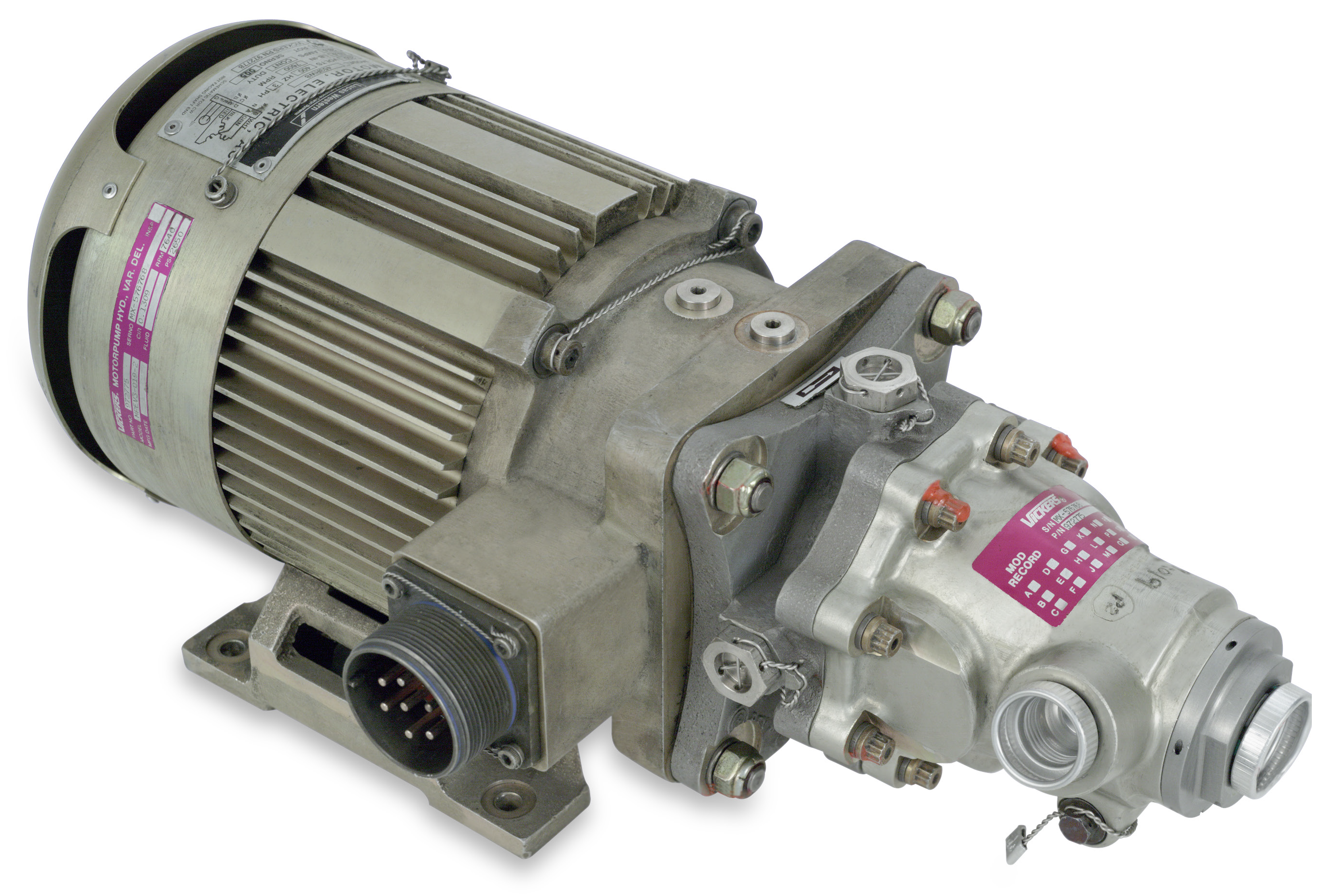 Eaton’s Vickers Model MPEV3-019-2 AC motor pump. Source: Eaton (Click image to enlarge)
Various types of electric motors are utilized in electric motor-driven hydraulic pumps including AC fixed or variable frequency motors and DC brushed or brushless motors. Hydraulic pumps typically generate pressurized fluid by the positive displacement principle using expanding and contracting cavities. Hydraulic pump types include gear pumps, rotary vane pumps, radial piston pumps and axial piston pumps.
How it works
To understand how a pressure-compensated electric motor-driven axial piston hydraulic pump works, we will examine the operating principles of Eaton’s Vickers Model MPEV3-019-2 AC motor pump. The model MPEV3-019-2 is a variable displacement inline axial piston hydraulic pump driven by an air-cooled electric motor. Model MPEV3-019-2 is designed to supply hydraulic power on aircraft. For example, it has received approval for cargo door actuation on cargo conversion aircraft like the DC-8-60.
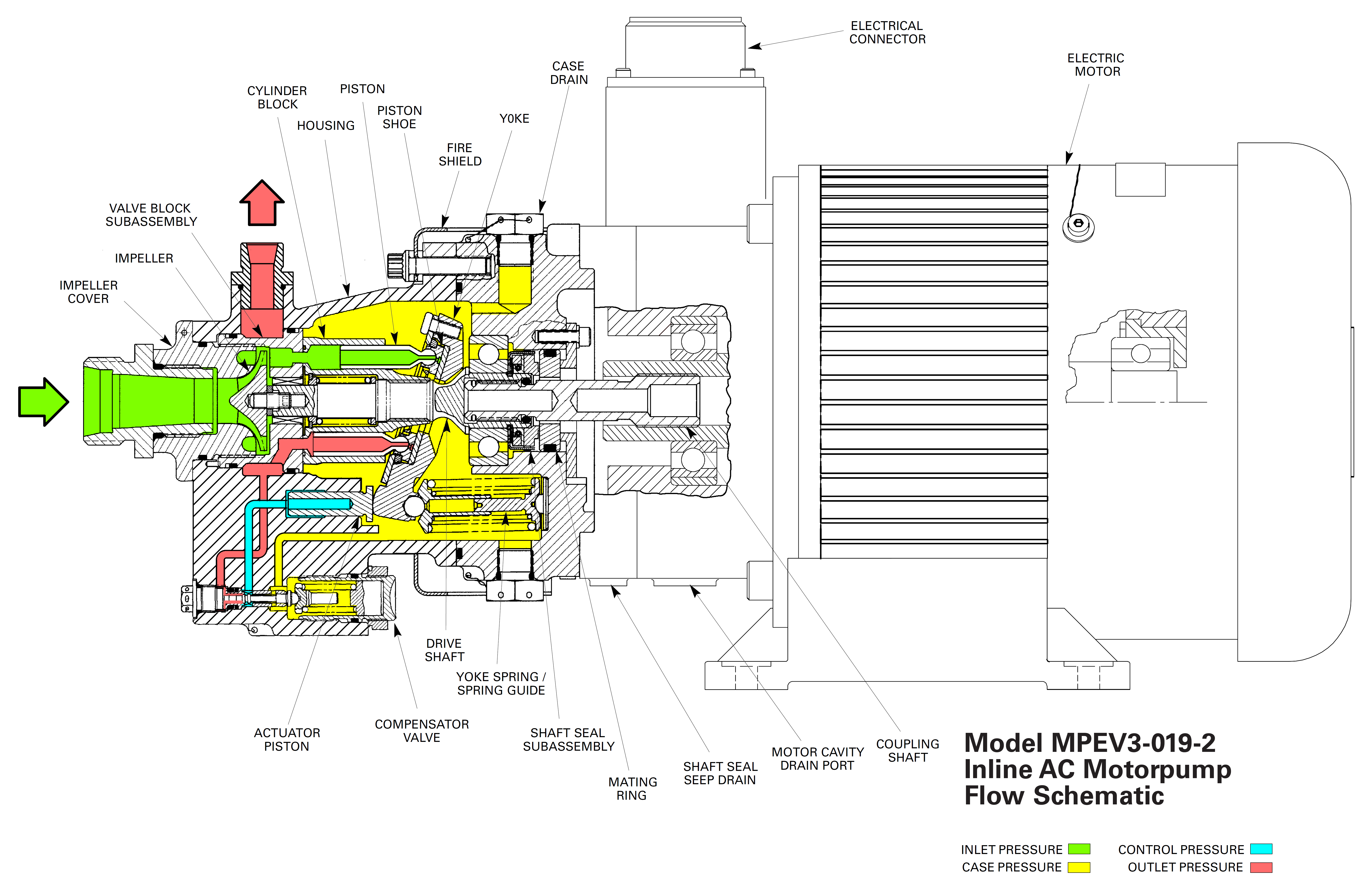 A schematic of Eaton’s Vickers Model MPEV3-019-2 AC motor pump. Source: Eaton (Click image to enlarge)
The hydraulic pump consists of an impeller boost stage that delivers pressurized flow to the piston pump. The electric motor directly drives both the impeller and piston pump by means of a rotating drive shaft. The drive shaft spins the impeller and rotates the cylinder block which contains the pistons.
As cylinder block rotation proceeds, the angled yoke, or swashplate, forces the pistons to move within the cylinder block bores, generating a single intake and discharge stroke for each piston per revolution of the drive shaft. Pistons are anchored to the yoke by means of piston shoes held in place by a retaining plate. During the intake stroke, pressurized fluid from the impeller floods into the cylinder bore. The discharge stroke produces high-pressure fluid as the fluid in the cylinder is compressed and forced out of the outlet. The model MPV3-019-2 is designed to minimize pressure ripple in the pump, with nine pistons in total.
 A zoomed view of the hydraulic section of Eaton’s Vickers Model MPEV3-019-2 AC motor pump. Source: Eaton (Click image to enlarge)
Pressure compensator
The pressure compensator adjusts pump output (volume flow rate) to maintain constant outlet pressure by varying pump displacement. It consists of a spool valve that controls flow to an actuator piston that controls yoke angle based on the compensator spring setting.
Diminished system flow demand will cause the outlet pressure to exceed the compensator spring setting. In this case, the force of outlet pressure against the compensator spool causes the spring to compress, shifting the spool and opening an orifice to deliver high-pressure fluid from the pump outlet to the actuator piston to reduce the yoke’s angle relative to the drive shaft. This results in shorter piston strokes, reducing pump displacement and decreasing pump output flow.
Rising system flow demand causes outlet pressure to drop. As outlet pressure drops back to the preset value, the spool shifts back, cutting off the supply of high-pressure fluid from the pump outlet to the actuator piston, causing the yoke to return to its maximum angle. This results in longer piston strokes, increasing pump displacement and pump output flow.
At outlet pressures below the preset value, the yoke is held at its maximum angle by a yoke return spring. In this condition, the pump operates at its maximum displacement until outlet pressure rises above the preset value.
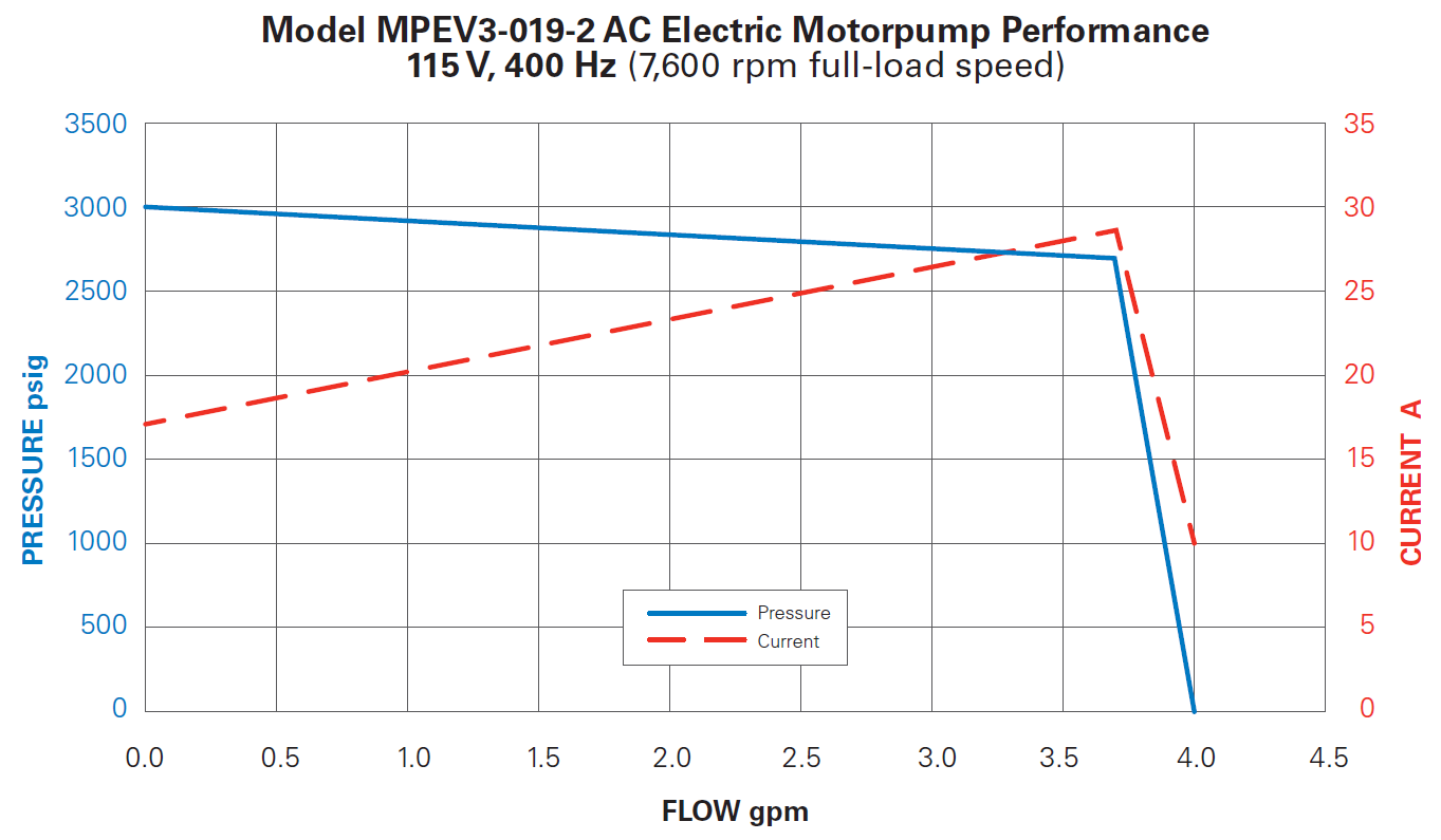 Performance graph plotting pressure and current versus flow rate for the Model MPEV3-019-2 AC motor pump. Source: Eaton (Click image to enlarge)
Application: more-electric aircraft
Electric motor-driven hydraulic pumps are increasingly important in the aerospace industry as aircraft manufacturers electrify functions on board aircraft to meet the growing trend toward more-electric aircraft (MEA). The motivation to convert mechanical, pneumatic and hydraulic systems to electric systems is driven by a desire to optimize aircraft performance, reduce maintenance and operating costs, increase fuel efficiency and reduce emissions.
Boeing’s 787 is an example of MEA in action. With the 787, Boeing modified part of the hydraulic system to be powered by electric motors instead of pneumatic power bled from the engines.
The 787 has three hydraulic systems on the aircraft that collectively power the actuation of primary flight control surfaces, leading and trailing edge flaps, landing gear, nose gear steering and thrust reversers. The left and right hydraulic systems are powered by engine-driven pumps with supplemental power from electric motor-driven hydraulic pumps during peak loads.
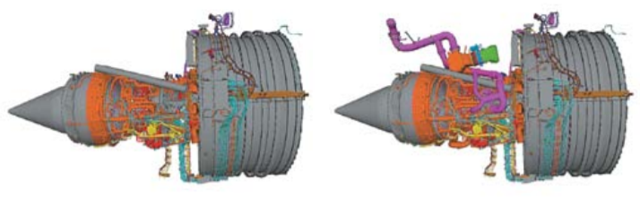 No-bleed engine (left) and traditional bleed engine (right). The no-bleed engine buildup is significantly simplified since components for the pneumatic bleed air system are eliminated. Source: Boeing
The 787’s center hydraulic system is powered by two electric motor-driven hydraulic pumps, each rated to produce around 30 gpm at 5,000 psi. This is in contrast to traditional systems on older aircraft that had a center system powered by two air turbine-driven hydraulic pumps delivering around 50 gpm at 3,000 psi during takeoff and landing as well as two small electric motor-driven hydraulic pumps delivering around 6 gpm at 3,000 psi for the rest of the flight. The switch to only electric motor-driven hydraulic pumps for the center system and the higher system pressure reduces overall weight and saves space due to smaller hydraulic components.
The improved system is part of the 787’s no-bleed systems architecture, which greatly reduces the bleed air architecture in which high speed air is diverted from the engines, reducing engine thrust and increasing engine fuel consumption. Engine-driven electrical systems are more efficient than bleed air pneumatic systems because pneumatic systems typically bleed more power than needed, resulting in excess pressurized air discharged into the atmosphere.