Back to the basics for calculating fluid flow through an orifice plate
Temitayo Oketola | October 31, 2021An orifice plate is a metal disk with a concentric hole in it, which, when inserted in a pipe, restricts fluid flow and reduces pressure. Orifice plates are vital in industries that handle liquid and gaseous products as they form the basis of fluid flow measurement in orifice flow meters.
As simple as this device seems to operate, a lot of work goes into designing and specifying orifice plates for specific applications. This article will cover the fundamental principles and calculations for correlating flow rate through an orifice plate.
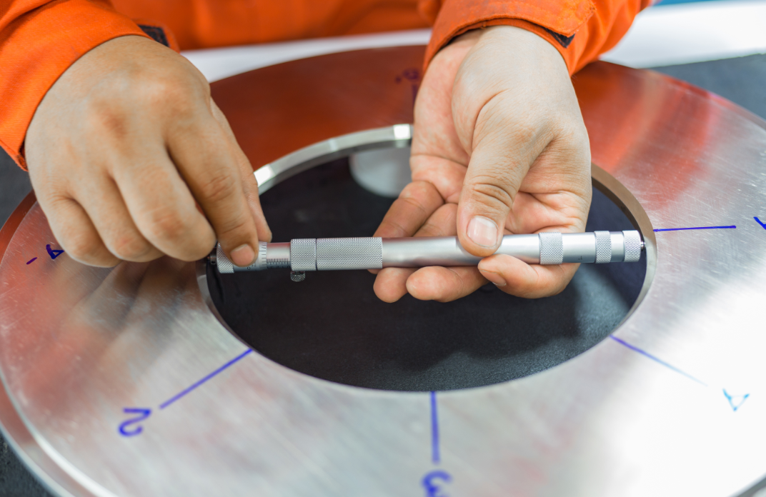 Figure 1: An inspector measuring the flow area diameter of an orifice plate. Source: pichitstocker/Adobe Stock
Fluid flow in pipe and the conservation of mass
Consider a steady flow of fluid in a pipe of diameter d1 that is constricted to a flow area of diameter d2 using an orifice plate, as shown in Figure 2.
![Figure 2: Fluid flow in a pipe that is constricted using an orifice plate. Source: Mbeychok/CC [SA][3.0]](/images/assets/606/17606/Fig2.png) Figure 2: Fluid flow in a pipe that is constricted using an orifice plate. Source: Mbeychok/CC [SA][3.0]
Figure 2: Fluid flow in a pipe that is constricted using an orifice plate. Source: Mbeychok/CC [SA][3.0]
Due to the steady-flow nature of the fluid flow, the conservation of mass principle requires that the total rate of mass entering through the inlet of this pipe equals the total rate of mass exiting through the outlet. This principle can be expressed mathematically as:

Where:
m1 = mass flow rate at the inlet of the pipe (kg/s)
m2 = mass flow rate at the outlet of the orifice plate (kg/s)
ρ1 = density of fluid at the inlet of the pipe (kg/m3)
ρ2 = density of fluid at the outlet of the orifice plate (kg/m3)
V1 = flow velocity at the inlet of the pipe (m/s)
V2 = flow velocity upstream of the orifice plate (m/s)
For incompressible fluids (usually the case for liquids), the density remains constant during fluid flow. Therefore, the conservation of mass equation becomes:

Where:
A1 = cross-section area of the pipe downstream of the orifice plate (m2)
A2 = cross-section area of the hole on the orifice plate (m2)
u = volume flow rate (m3/s)
Orifice plate and the Bernoulli’s Obstruction Theory
As the incompressible steady-flow fluid passes through the orifice, pressure builds up due to flow restriction, causing the fluid velocity to increase according to Bernoulli’s equation.

Where:
P1 = pressure value upstream of the orifice (Pa)
P2 = pressure downstream of the orifice (Pa)
ρ = mass density of fluid (kg/m3)
g = gravitational acceleration (m/s2)
z = elevation (m)
V1 = flow velocity downstream of the orifice plate (m/s)
V2 = flow velocity upstream of the orifice plate (m/s)
As Bernoulli’s equation suggests, the flow velocity downstream of the orifice plate can be obtained by measuring the difference in pressure values immediately before and after the orifice plate.
By combining the conservation of mass equation with Bernoulli’s equation and solving for V2, we obtain:

Where:
β = ratio of pipe diameter to orifice diameter (d1/d2)
The volume flow rate at the orifice plate can then be expressed as:

Where:
A2 = flow cross-section area at the orifice plate (m2)
Pressure loss due to orifice plate
In reality, there is always some pressure loss due to frictional effects when fluid passes through orifice plates. As a result, the fluid flow velocity (and flow rate) at the exit of the orifice plate is always less than what was calculated in the previous section. Engineers account for these losses using a discharge coefficient parameter, Cd, whose value is less than 1. Thus, the flow velocity and flow rate equations become:

A discharge coefficient of 1 would translate to a theoretically perfect orifice plate having no losses (see Figure 3).
![Figure 3: Fluid flow across a theoretically perfect orifice plate. Source: Motorhead/CC [SA][3.0]](/images/assets/606/17606/Fig3.png) Figure 3: Fluid flow across a theoretically perfect orifice plate. Source: Motorhead/CC [SA][3.0]
Figure 3: Fluid flow across a theoretically perfect orifice plate. Source: Motorhead/CC [SA][3.0]
Keep in mind that the maximum flow velocity doesn’t occur at the orifice hole, but instead at a region called the “vena contracta.” This is because the cross-section area of the fluid flow continues to reduce as the fluid passes through the orifice plate until it reaches the vena contracta, where its area is least (see Figure 4).
![Figure 4: Actual flow area as the fluid passes through an orifice plate. Source: Motorhead /CC [SA][3.0]](/images/assets/606/17606/Fig4.png) Figure 4: Actual flow area as the fluid passes through an orifice plate. Source: Motorhead /CC [SA][3.0]
Figure 4: Actual flow area as the fluid passes through an orifice plate. Source: Motorhead /CC [SA][3.0]
Orifice plates are extremely accurate devices, suitable for many fluid flow measurement applications provided that they are correctly specified. While this article provides useful information about the design process, engineers and product designers are advised to check the AGA 3.1 and ISO 5167-2 standards for more information about sizing and specifying orifice plates.