
Fan anatomy
September 01, 2026Every part of a fan plays a role in how it performs. This article takes a closer look at the fan anatomy that generates airflow.
While there are many components, accessories and modifications available, industrial fan assemblies can be intuitive once you break down the basic anatomy of a fan.
Let’s start by taking a look at the drive train of a direct-driven, arrangement 8 centrifugal fan since it includes most of the basic components found in different assemblies.
The drive train starts with a driver; typically an electric motor. The motor creates rotational force that spins a fan’s wheel. Motors can be mounted in a few different ways, including a direct connection from the motor shaft to the wheel, a belt-driven connection using belts and pulleys, or in the case of an arrangement 8 fan, a coupled connection.
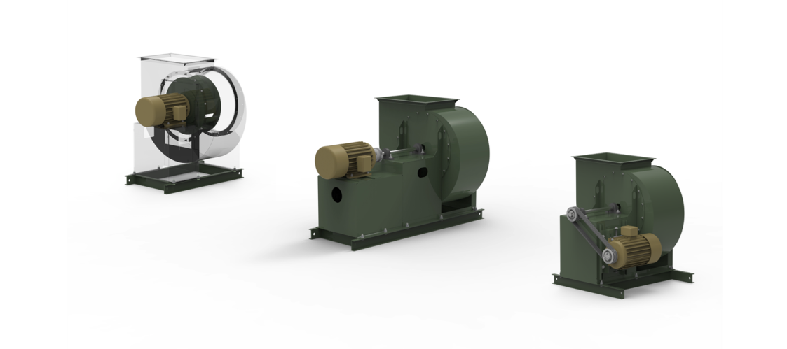 Figure 1: The motor shaft connects to a fan shaft through a coupling. Source: The New York Blower Company
The motor shaft connects to a fan shaft through a coupling. The coupling has two hubs, one for the motor shaft and one for the fan shaft, and a housing to contain and connect the two.
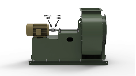 Figure 2: Bearings. Source: The New York Blower Company
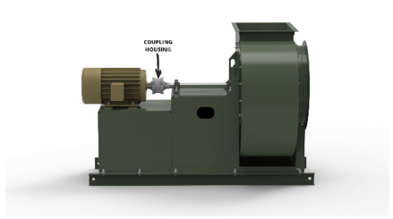 Figure 3: Bearings. Source: The New York Blower Company
A pair of bearings support the load of the fan shaft and the wheel, allowing the driver to rotate the wheel and shaft assembly.
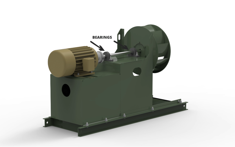 Figure 4: The fan shaft connects to the wheel’s hub, completing the drive train. Source: The New York Blower Company
The fan shaft connects to the wheel’s hub, completing the drive train. That connection can be secured in a few different ways. Bushed hubs use a bushing, which is typically a split taper design, fitting into a hub with a machined taper.
Another common connection is a close tolerance fit, which does not use a taper, but instead uses set screws to fasten the wheel’s hub to the fan shaft.
Finally, an interference fit uses a fan shaft with a slightly larger diameter than the hub’s bore. The shaft can be cooled for contraction, or the hub can be heated for expansion, allowing the two components to fit together before returning to their normal size, ensuring a very tight connection.
A housing surrounds the wheel, which has an expanding scroll, or, volute, a drive side facing the drive train and an inlet side where air is pulled into the wheel.
Backward inclined fans use inlet cones to smoothly move air into the housing at the center of the wheel for the most efficient performance. An inlet cone reduces pressure loss as air is pulled toward the wheel, which is essential for the fan to meet its intended performance.
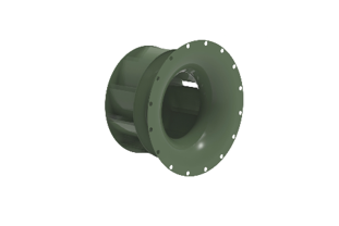 Figure 5: Radial bladed fans. Source: The New York Blower Company
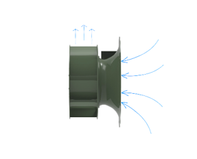 Figure 6: Radial bladed fans. Source: The New York Blower Company
Radial bladed fans use a straight pipe inlet design for air to enter the housing, as the wheel geometry is much more tolerant of non-uniform flow.
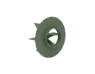 Figure 7: Radial bladed fans. Source: The New York Blower Company
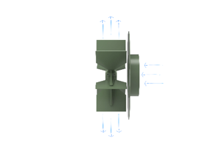 Figure 8: Radial bladed fans. Source: The New York Blower Company
As air enters the fan and the wheel rotates, it accelerates airflow radially toward the housing scroll. The air then starts to travel along the volute, slowing down with its expansion, finally discharging from the fan outlet.
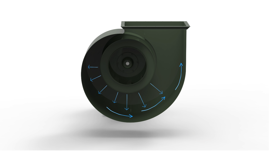 Figure 9: Centrifugal fan. Source: The New York Blower Company
Some centrifugal fans utilize a cut-off sheet, which prevents air from recirculating within the housing.
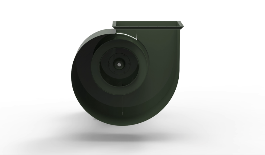 Figure 10: Some centrifugal fans utilize a cut-off sheet. Source: The New York Blower Company
Finally, there are the structural supports of a fan. Pedestals support the motor and bearings and are connected to the drive side of the housing by a bolted or welded connection. The bottom perimeter of the pedestal has flanges for securely mounting the assembly. A bolted connection allows the fan to be installed into a system or connected to a unitary base or sub-base that supports the mounting of motors, inlet boxes, silencers and filters.
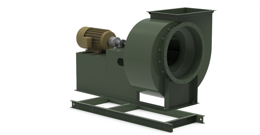 Figure 11: Fans utilize a driver that rotates a wheel via various connections that move airflow as efficiently as possible. Source: The New York Blower Company
While various arrangements use these components differently, the concepts are fundamentally the same. Fans utilize a driver that rotates a wheel via various connections that move airflow as efficiently as possible. To better understand the nuances of different fan configurations, watch the accompanying “Fan Fundamentals” video on fan arrangements.