Vacuum ejector: Understanding its working principle and some design parameters
Temitayo Oketola | April 29, 2022Vacuum ejectors, or simply ejectors, are a type of vacuum pump that produces vacuum by means of the venturi effect. However, unlike mechanical vacuum pumps, vacuum ejectors do not contain any moving parts; they use a working fluid (usually a gas that is made to flow through a jet nozzle) as a source of power to move a secondary fluid.
This mode of operation makes them more compact, lightweight and cost-effective than their mechanical counterparts.
This article covers the basic working principle of vacuum ejectors, particularly the simple, single-stage type. It will also provide some key design calculations that engineers should know about these vacuum-providing devices.
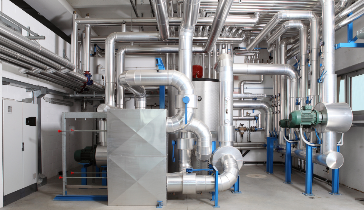 Vacuum pumps are heavily relied on in modern-day refrigeration systems. Source: visivasnc/Adobe Stock
Working principle of vacuum ejectors
A typical single-stage ejector is made up of the following essential components:
- Nozzle
- Suction chamber
- Mixing section
- Diffuser
![A single-stage vacuum ejector illustration. Source: Mbeychok/CC [SA] [3.0]](/images/assets/359/18359/Vacuum2.png) A single-stage vacuum ejector illustration. Source: Mbeychok/CC [SA] [3.0]
A single-stage vacuum ejector illustration. Source: Mbeychok/CC [SA] [3.0]
A high-pressure gas (also known as motive gas) is supplied through the opening of the ejector at low velocity and made to flow through a jet nozzle. As the motive gas flows through the nozzle, its pressure energy (available upstream of the nozzle) is converted into kinetic energy, resulting in low-pressure high-velocity gas exiting the jet nozzle and creating a vacuum.
This vacuum draws in the secondary fluid through the suction inlet of an outer tube (as shown in Figure 2). The high-velocity motive fluid from the jet nozzle entrains and mixes with this secondary fluid stream, imparting enough kinetic energy for the mixture to be ejected through the outlet of the outer tube. Keep in mind that the outer tube is gradually expanded downstream (to form a diffuser), causing the discharge pressure of the mixture to increase to up to 15 times the suction pressure.
Some key parameters in ejector design
1. Entrainment ratio
The performance of an ejector is usually described in terms of mass entrainment ratio, which can be calculated using:
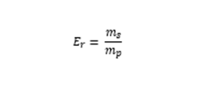
Where:
Er = entrainment ratio
ms = mass flow of secondary fluid (kg/s)
mp = mass flow of the motive or primary fluid (kg/s)
The entrainment ratio describes the carrying capacity of the motive gas or simply the pumping performance of the ejector. High entrainment ratios cause shock waves to be shifted away from the mixing section, enhancing the suction of the secondary fluid stream.
2. Area ratio
Ejector structure is usually characterized by the area ratio, which is defined as the ratio between the cross-section area of the mixing section and the cross-section area of the primary nozzle throat. The area ratio also affects the efficiency of ejectors since increasing this ratio results in a corresponding increase in the entrainment ratio and reduction of backpressure.
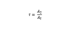
Where:
T= area ratio
A2 = cross-section area of the mixing section (m2)
At = cross-section area of the primary nozzle throat (m2)
The area ratio can be increased by reducing the primary nozzle throat area or increasing the mixing section area, with the former being the more general practice by ejector designers. To adjust the primary nozzle throat area, many ejector manufacturers implement a moveable spindle inside the primary nozzle throat, allowing them to meet different operational requirements.
3. The velocity of the mixed fluid streams
In the thermodynamics-based analysis of most ejector designs, the motive and secondary fluid streams are assumed to be mixed at constant pressure in the mixing chamber. Also, by assuming that the two fluid streams are completely mixed at the throat of the mixing chamber, engineers can easily estimate the velocity of the mixed fluid streams using the momentum equation.
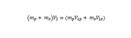
Where:
mp = mass flow of the motive fluid (kg/s)
ms = mass flow of the secondary fluid (kg/s)
V2 = velocity of the mixed fluid streams at the mixing chamber (m/s)
V1p = velocity of the motive fluid at the exit of the primary nozzle (m/s)
V1s = velocity of the secondary fluid at the suction inlet (m/s)
Engineers can also estimate the velocity of the mixed fluid streams by including the entrainment ratio parameter in the momentum equation, as shown in the equation below:
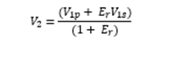
Where:
Er = Entrainment ratio
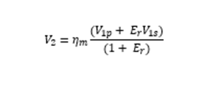
One thing to note, though: there is always a loss in velocity of the mixed fluid stream. Engineers can account for this loss by including a mixing efficiency parameter, nm, which typically ranges between 85% and 95%. Hence, a better approximation of the secondary flow velocity would be:
The design process of vacuum ejectors is iterative, requiring a lot of design modifications for best performance. Engineers are advised to set some design specifications during the early design stage, for example, the flow rate, pressure and temperature values of the motive gas.