Steps to Correctly Select Water Treatment Systems
Brad Buecker | September 15, 2015In the 35 years I have been in the industry, and especially in the last five, I have observed many new plant specifications in which water treatment, chemical feed, and water/steam chemistry monitoring systems were improperly designed.
It is often obvious that selections are made by owners and owner’s engineers who are not familiar with modern concepts and treatment methods. This lack of knowledge regularly leads to selection of outdated technologies, under-design of some systems and, more often than one might expect, over-design of others. The consequences can be severe and may range from installing systems that do not work properly from day one and must be replaced to selecting chemistry treatment programs that do not protect makeup water/cooling water/steam generation systems and allow corrosion and fouling.
This article aims to provide an incentive for those preparing new plants to consider retaining expert personnel early in the plant design to perform a plant or specification audit to ensure that the selections are correct from the beginning.
First, consider raw water analyses. Comprehensive and historical data are imperative for proper design of plant makeup water systems. Often, however, specifications arrive with incomplete data or no data at all. The owner’s engineer may say, “Design to a standard water.” There is no such thing. Even seemingly benign surface water supplies experience significant chemistry changes. Heavy rains can stir up suspended solids, while “turnover” in lakes and reservoirs bring impurities to the surface that may have lain dormant for months.
With increasing frequency, plant personnel choose alternatives to fresh water supplies for makeup. One such alternative is municipal wastewater treatment plant (WWTP) effluent. These supplies can contain varying concentrations of ammonia, phosphate, organic materials and suspended solids. In other situations, a deep aquifer may be tapped for makeup water. These supplies often contain high concentrations of dissolved solids, which may include hardness, silica and chloride, and which might eliminate such technologies as reverse osmosis (RO) as a treatment option.
Thus, comprehensive data are necessary to select the proper treatment system. In some cases, I have seen clarifiers specified as part of the makeup water system (primarily for suspended solids removal) when micro- or ultrafiltration would be sufficient. Conversely, a lime/soda ash softening clarifier may be the appropriate choice for waters with high hardness (calcium and magnesium) and alkalinity. Here, however, many people still envision outdated clarifier design with rise rates at or near 1 gpm per square foot of surface area. Depending upon the inlet makeup water flow, these clarifiers may have an enormous footprint. Now available are high-rate clarifiers that utilize sludge recirculation or ballasted recycle feed that have much higher rise rates and are much smaller.
Working with Municipal Wastewater
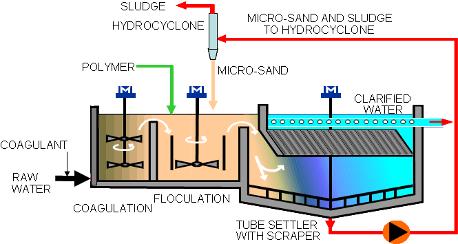 (Click to enlarge) High-rate ballasted sand clarifier. Image source: Veolia Water Technologies.In cases where the makeup comes from a municipal WWTP, I have encountered confusion about how to deal with this water. A common treatment method for removing small concentrations of ammonia is breakpoint chlorination, where bleach can be injected at a sufficient concentration to convert ammonia to nitrogen. However, ammonia levels in WWTP effluent may be as high as 30-40 parts-per-million (ppm). To achieve breakpoint chlorination would require a feed of truckloads of bleach per day. A wiser choice, and one that is becoming more common, is biological treatment as personified by membrane bioreactors (MBR) and moving bed bioreactors (MBBR).
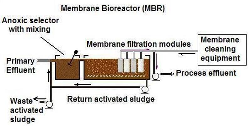 (Click to enlarge) General outline of one variation of MBR. Source: www.wrights-trainingsite.com
Through my direct experience with conventional activated sludge treatment, I believe that MBR and MBBR offer several advantages. Microbes that consume ammonia, organics and phosphorus are grown within vessels either in a suspended mode or attached to mobile media. Impurity concentrations can be reduced to low ppm levels, with final treatment by MF or UF to produce an effluent virtually free of suspended solids. Depending upon the extent of treatment needed, most of the ammonia can be converted to nitrate or elemental nitrogen.
Another difficulty that often occurs is selecting cooling tower operating conditions without due consideration given to the fundamentals of tower operation or makeup water chemistry. For example, a specification may arrive with a requirement to design the water balance to say 10 cycles of concentration or higher in the tower. It seems apparent that the designer is locked into the mindset that a high number of cycles equates to a large reduction in blowdown quantity. However, as the graph illustrates, this is rather illusory.
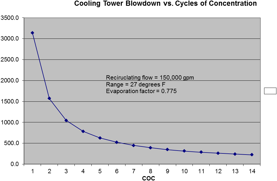 Cooling tower blowdown vs. cycles of concentration for the example conditions shown.The savings at 10 COC as compared to a common maximum range of 6 to 8 COC are minimal. Also, as COC is increased, the chemistry of the cooling water and treatment methods become more complex due to concentration of impurities. Saturation limits may be approached or exceeded for any of a number of scale-forming constituents including calcium carbonate, phosphate and sulfate, magnesium silicate and others. Chemical treatments may be effective only to certain limits.
Sidestream Filtration
Also with regard to some cooling tower proposals, the specifications arrive with a requirement for makeup water filtration. However, what some designers often forget is that cooling towers are superb air scrubbers and the majority of particulates that accumulate in the cooling water may come from the atmosphere. A more logical choice, and one that is often recommended for large towers, is sidestream filtration.
As the name implies, the filter treats a side stream from the tower (perhaps 1-10% of the circulating rate) and returns the filtered water to the system. A variety of filter types have been used for this purpose, including multi-media filters, rapid sand filters, disc filters and even microfilters.
Finally, I will discuss an issue that continues to appear regarding combined-cycle power plants and almost certainly is an issue with co-generation steam generators.
In the middle of the last century, researchers and chemists believed that dissolved oxygen in the condensate/feedwater of steam generators caused huge problems, and that all oxygen should be eliminated by mechanical deaeration and feed of oxygen scavengers (more properly known as reducing agents). Indeed, for those systems that contain copper alloys, typically feedwater heater tubes, dissolved oxygen can cause severe corrosion of the alloy.
However, what has become well known over the last 30 years is that feed of an oxygen scavenger can generate flow-accelerated corrosion (FAC) of carbon steel. In the last three decades, a number of FAC-induced failures have killed plant personnel. So, for systems that do not have copper alloys in the condensate/feedwater system, which includes virtually all combined-cycle plants (and perhaps many co-generation steam generators), alternative programs have been developed in which no oxygen scavenger is utilized. With high-purity water (less than 0.2 µS/cm cation conductivity) and a small amount of dissolved oxygen, carbon steel forms a protective coating. However, I continue to see combined-cycle specifications that call for an oxygen scavenger feed system. This seems to be a mindset that simply will not disappear.


