Low pressure filtering of a pressure sensor's input
June 26, 2020The problem
 Figure 1: The experimental test set up. Source: All SensorsIn some applications, high-frequency pressure transients may be present that distort the sensor’s output and degrade its ability to read the underlying changes in pressure. This can especially be a problem in low-pressure applications, such as medical measurements where discerning subtle differences is essential to successful diagnosis and monitoring. Previously, a common, well-known solution was not available, but one has now been found.
The solution
The proposed solution involves the application of an electrical or hydraulic analogy to a pneumatic system. To filter the pressure transients, an inline reducer is used, similar to how a capacitor filters the voltage transients in an electrical circuit.
The proof
Several laboratory measurements were made to verify the effectiveness of the proposed solution. The experimental setup included an All Sensors’ DLHR-F50D sensor installed on an EK-01 evaluation board, a signal generator waveform source and an oscilloscope as shown in Figure 1. The signal generator was connected to drive an earphone speaker, which was first connected to a short length (7 cm) of ¼ in outer diameter (OD) silicone tubing and then through 1/8 in tubing (10 cm) to the sensor port. A 1/8 in national pipe thread (NPT) to 1/8 in inner diameter (ID) barb fitting and a 1/8 in ID to 1/16 in ID barb reducer connected the segments. See Figure 2.
 Figure 2: (a) Tubing without restriction and (b) tubing with restriction. Source: All SensorsTo identify the filtering behavior above and below the limit of the effective sensor sample rate, a set of audio frequencies was selected. In Sync reading mode, a DLHR sensor with an 18 bit configuration will typically execute 270 readings per second. Correctly reading the waveform amplitude requires at least five samples per period, so a signal waveform of 270/5 or 54 Hz or slower can be identified correctly in both frequency and amplitude.
For these measurements, readings were taken with and without the restriction in place. The restriction consisted of a Nordson EFD dispensing tip, part 7018272 as shown in Table 1. Note that the tip is pointed in the direction of the audio source when in place and the 0.4 mm ID represents a restriction in cross-section of 0.412/3.182 or a channel of 1.66% of the source area.
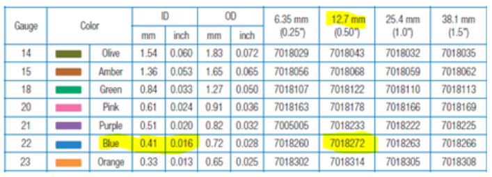 Table 1: EFD dispensing tip dimensions. Source: EFD
A baseline measurement at 10 Hz confirmed sensor operation and the test set up. (See Figure 3.) A waveform period of approximately 27 samples at 10 Hz corresponds to about 270 samples per second.
 Figure 3: The 10 Hz baseline. Source: All Sensors
Absolute reading values are not significant, since the audio signal is not constant with a change in frequency. Relative readings with and without restriction are of interest. The following measurements include a reference reading, including only the tubing of Figure 2 (a) in the audio path compared with readings with the restriction inserted in the line at the reducer fitting (Figure 2 (b)).
Figures 4 and 5 show the results of testing at 30 Hz. With tubing only, the 30 Hz signal has an amplitude of about 0.55% frequency selective surface (FSS). With the restriction, a 30 Hz signal has an amplitude of about 0.50% FSS, down 0.8 dB from the reference. A more regular waveform suggests that higher-frequency noise components are reduced.
 Figure 4: 30 Hz reference: Source: All Sensors
 Figure 5: 30 Hz measurement with restriction. Source: All Sensors
Figures 6 and 7 show the results of testing at 50 Hz. With tubing only, the 50 Hz signal is near the limit of accurate sampling and has an amplitude of about 1.0% FSS. With the restriction, a 50 Hz signal has an amplitude of approximately 0.80% FSS or about -2 dB from the reference.
 Figure 6: 50 Hz reference: Source: All Sensors
 Figure 7: 50 Hz measurement with restriction. Source: All Sensors
Figures 8 and 9 show the results of testing at 100 Hz. With the tubing only, the 100 Hz signal is beyond the point of identifying a period. The envelope amplitude is about 2.6% FSS. With the restriction, the 100 Hz signal has an amplitude of approximately 1.6% FSS, or about -4.2 dB from the reference.
 Figure 8: 100 Hz reference. Source: All Sensors
 Figure 9: 100 Hz measurement with restriction. Source: All Sensors
Figures 10 and 11 show the results of testing at 240 Hz. At 240 Hz, the amplitude of the reference signal increases to 20% FSS. With the restriction in place, at 240 Hz the amplitude drops to about 3.4% FSS, 15 dB from the reference.
 Figure 10: 240 Hz reference. Source: All Sensors
 Figure 11: 240 Hz measurement with restrictions. Source: All Sensors
Figures 12 and 13 show the results of testing at 600 Hz. At 600 Hz, the amplitude of the reference signal is about 5.1% FSS. With the restriction in place, at 600 Hz the amplitude is reduced to approximately 1.0% FSS, -14.2 dB from reference.
 Figure 12: 600 Hz reference: Source: All Sensors
 Figure 13: 600 Hz measurement with restriction. Source: All Sensors
While there is little available information regarding pneumatic low-pass filter models as proposed, the concept appears to be valid. Table 2 shows the results for the various frequencies tested.
 Table 2: Pneumatic filtering for low pressure sensor transients. Source: All Sensors
The conclusion and recommendation
High-frequency pressure transients may be present and especially problematic in low-pressure applications. Laboratory tests have demonstrated the effectiveness of inserting an inline restriction to reduce pressure transients. A 0.41 mm diameter restriction appears to provide an effective barrier to higher-frequency pressure transients, while allowing lower-frequency pressure changes to pass with little change in magnitude. In this case, the corner frequency can be estimated at around 120 Hz to 140 Hz.
Users who have encountered or are concerned with low pressure transients should evaluate the effectiveness of a restriction in their specific application. The combination of restriction diameter with the volume of tubing downstream must be considered in evaluating the filter properties, since that volume represents the compliant storage element analogous to a capacitor or hydraulic accumulator.
Changes in tubing length between the sensor and the restriction are therefore expected to change the corner frequency of the pneumatic filter, so each application must verify the performance using the tubing configuration of the final design.


