What is a klystron?
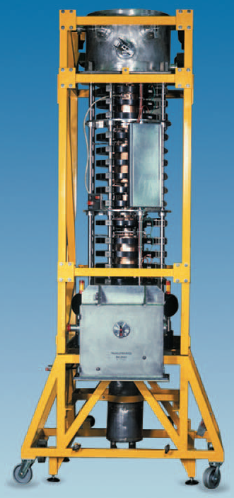
Eric Olson | October 03, 2019 An L-band klystron that provides RF power at 1.3 GHz to the electron guns and linac accelerating structures in the Argonne Wakefield Accelerator (AWA). Source: Argonne National Laboratory
Klystrons are linear-beam vacuum tubes used to amplify radio frequencies. The devices are effective over a broad range of frequencies ranging from hundreds of MHz (i.e., UHF) to hundreds of GHz (i.e., W-band microwaves and above). Klystrons operate at narrow bandwidths, typically between 1% and 10%, with high gain (e.g., 60 dB or more is possible).
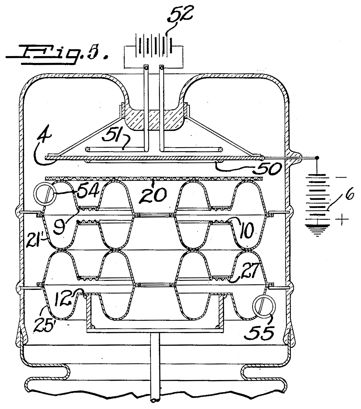 A longitudinal sectional view of the amplifier tube from U.S. patent 2,242,275 filed by Russell H. Varian on Oct. 11, 1937 and granted May 20, 1941. Source: U.S. Patent and Trademark Office (Click image to enlarge)The development of the klystron was motivated by a desire to surpass the frequency and power limitations of earlier amplifying vacuum tubes like triodes and tetrodes. Klystrons were invented by brothers Russell and Sigurd Varian who were searching for a compact source of high-frequency power to drive high-frequency transmitters on airplanes to enable “blind” landings, or landings in which the pilot references the airplane’s instruments only, instead of visual observation of the environment. A patent for an “electrical translating system and method” that contained the design for a klystron was filed by Russel H. Varian in October 1937 and granted in May 1941.
“Klystron” is a portmanteau of the Greek verb κλύζω (“klyzo”) – which refers to the action of waves breaking against a shore – and the suffix -τρον ("tron") – which refers to the place where the action happens.
Klystrons belong to the same family of linear-beam tubes as traveling-wave tubes (TWTs). Compared to klystrons, TWTs operate at higher bandwidths.
[Discover products, standards and information related to klystrons on Engineering360.]
 An early klystron manufactured by Westinghouse with part of its exterior cut away to reveal its internal structure. The device was capable of producing 200 W of RF energy at 750 MHz (40 cm wavelength) with an efficiency around 50%. Source: Electronics magazine, McGraw-Hill Publishing Co., New York, Vol. 13, No. 11, November 1940 (Click image to enlarge)
Klystron applications
 The Thales TH2167 continuous wave klystron outputs 300 kW of RF energy at 400 MHz. Sixteen of these klystrons serve as the RF power source for the Large Hadron Collider (LHC) at the European Organization for Nuclear Research (CERN) in Geneva, Switzerland. The RF power is used to accelerate LHC’s two counter-rotating proton beams to their ultimate energies of 2 x 6.5 TeV in a tunnel 27 km in circumference and buried 50 to 175 meters underground. Source: Thales (Click image to enlarge)Since the invention of klystrons, solid-state alternatives (e.g., Gunn diodes) have replaced low-power klystrons in some radar and communication applications, although klystrons’ high power density and efficiency sustain its relevance in many applications today.
Klystrons power transmitters for a variety of radars, including weather, military and air traffic control radars. The devices are also used in satellite communications. For example, the Deep Space Network’s (DSN) satellite terminal transmitters use klystrons for signal amplification. High-power UHF TV transmitters were driven by klystrons. In radiation oncology, klystrons provide microwave energy to treat tumors.
Klystrons are also an important tool in particle physics research. They are used as powerful sources of microwaves in particle accelerators such as synchrotrons to accelerate charged particles to high speeds for use in particle collision studies that investigate the nature of matter or as powerful x-ray sources. Synchrotron radiation enables research into condensed matter physics, materials science, chemistry and biological processes using x-ray diffraction, x-ray spectroscopy and other techniques.
[Discover x-ray fluorescence spectrometers on Engineering360.]
 A plot comparing the operating regimes of various RF amplifiers (e.g., tetrodes, RF solid state amplifiers (SSA), inductive output tubes (IOT) and magnetrons) to klystrons used in particle accelerators, including electron and proton rings, superconducting electron/proton linear accelerators and electron linear accelerators. Source: I. Syratchev, CERN (Click image to enlarge)
Klystron types
 The E3712 pulsed klystron is available with peak output power of 80 MW or 100 MW operating at 2,856 MHz. Source: Canon Electron Tubes & Devices
Since the invention of the klystron in 1937, many different types and designs have been developed. The most basic configuration is the two-cavity klystron. Most modern klystrons have multiple cavities (e.g. five or six) in a cascade arrangement to attain higher gain and efficiency.
Continuous wave (CW) klystrons operate with continuous output power while pulsed klystrons have a pulsed output. As an example of the performance characteristics of klystrons, Canon Electron Tubes & Devices’ series of CW klystrons operates with continuous output powers from around 30 kW to 1.4 MW at frequencies from 325 MHz to 5 GHz. Canon’s series of pulsed klystrons operates with peak output powers from around 100 kW to 100 MW and pulse lengths between 0.3 µs and 3,500 µs at frequencies from 324 MHz to 11.994 GHz.
Other advanced klystron designs include the multi-beam klystron (MBK), which uses multiple electron beams and waveguide circuits to boost RF power output, and the periodic permanent magnet (PPM) klystron, which accomplishes electron beam focusing with permanent magnets arranged so that the magnetic field changes direction periodically.
[Discover magnets on Engineering360.]
How does a klystron work?
Klystrons boost the power of RF signals by harnessing the energy of an electron beam. They convert the kinetic energy of electrons into electromagnetic wave energy to generate an amplified RF signal.
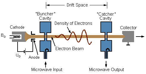 A simplified diagram of a two-cavity klystron. Source: Modified image based on a drawing by Christian Wolff/CC BY-SA 3.0
The basic process by which a two-cavity klystron amplifier operates is as follows.
- Electrons emitted by the cathode are accelerated by the anode toward the input cavity.
- The low-level RF input signal is coupled into the input resonator cavity, establishing standing waves. The oscillating electric field in the cavity accelerates some electrons and decelerates others as they cross the cavity’s gap.
- This velocity modulation causes fast electrons to catch up to slow electrons over the length of the drift space, resulting in the formation of electron bunches.
- Electron bunches arriving at the second resonator cavity induce standing waves. The oscillating electric field decelerates the bunches, converting kinetic energy to energy stored in the oscillating field.
- The amplified RF signal is collected through a coaxial cable or waveguide.
The operation of a two-cavity klystron tube is described in more detail below.
 A klystron serves as the source of high-power microwaves in this weather radar system. Source: Selecs (Click image to enlarge)
At one end of the tube, a uniform beam of electrons is generated at a cathode and accelerated by an anode to travel through the tube toward a collector at the other end. The beam is focused by external electromagnets to prevent the beam from spreading.
The electron beam first passes through an input resonator cavity into which the RF input signal has been coupled by means of a coaxial cable or waveguide. The input resonator cavity is designed so that its resonant frequency is near the frequency of the input signal. Standing wave oscillations are generated in the cavity at this resonant frequency.
[Discover RF waveguide components on Engineering360.]
At the opening and exit of the input cavity, through which the beam passes, are grids. Across the grids is an AC voltage that corresponds to the standing wave oscillations. This voltage produces an oscillating electric field across the gap in the cavity that modulates the velocity of the electrons. As the electric field oscillates, some electrons are accelerated and some are decelerated. Electrons speed up when the electric field is in the opposite direction as the motion of the electrons (i.e., when the exit grid is positive and the entrance grid is negative); electrons slow down when the electric field is in the same direction as the motion of the electrons (i.e., when the exit grid is negative and the entrance grid is positive). This is because electric field lines indicate the direction of the force acting on a positive charge, and electrons are negatively charged.
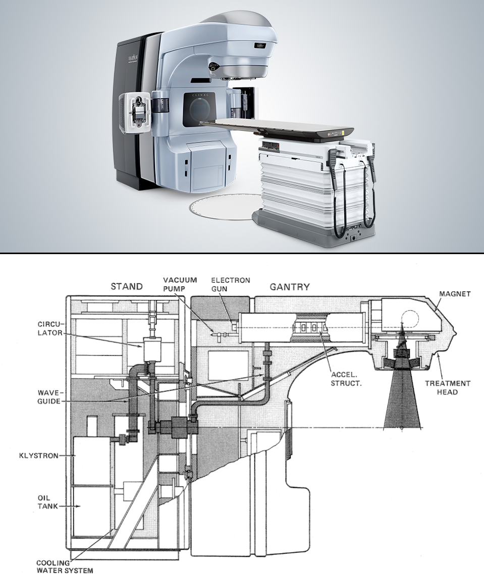 Top: The Varian Clinac iX linear accelerator system used in radiotherapy treatments for cancer. Bottom: A schematic showing a Clinac’s internal components. A klystron generates high-frequency microwaves which are carried by waveguides to an accelerator structure to accelerate electrons for a treatment beam, which is directed and shaped for precision delivery to the patient. Source: Varian (top), Karzmark and Morton (bottom) (Click image to enlarge)
The electrons exit the input resonator cavity and travel along the tube through the drift space. Over this distance, the faster electrons catch up to the slower electrons, forming bunches of electrons.
At the end of the drift space, the bunched electrons enter a second resonator cavity. The duration of time between the arrival of each bunch of electrons corresponds to the period of the RF signal input at the first cavity.
When designing the klystron, the length of the drift space is chosen so that the density of electrons in the bunches is highest at the moment they arrive at the second cavity. Bunches of electrons arriving at the second cavity induce standing waves in the cavity with the same resonant frequency as the input cavity. The electron bunches arrive at the second cavity when its oscillating electric field is in the same direction as the motion of the electrons (i.e., when the exit grid is negative and the entrance grid is positive). Hence, the bunches of electrons slow down as their kinetic energy is converted to energy stored in the oscillating field. The field strength is thus increased and the amplitude of oscillations is boosted. The amplified RF signal is collected through a coaxial cable or waveguide.
The electron beam then passes out of the second resonator cavity with reduced energy and is collected at the collector electrode. Depending on the efficiency and operating parameters of the klystron, a significant amount of energy can be left over in the depleted electron beam gathered at the collector. This energy is dissipated as heat, requiring cooling to keep the device within an acceptable operating temperature range.
[Discover RF amplifiers on Engineering360.]
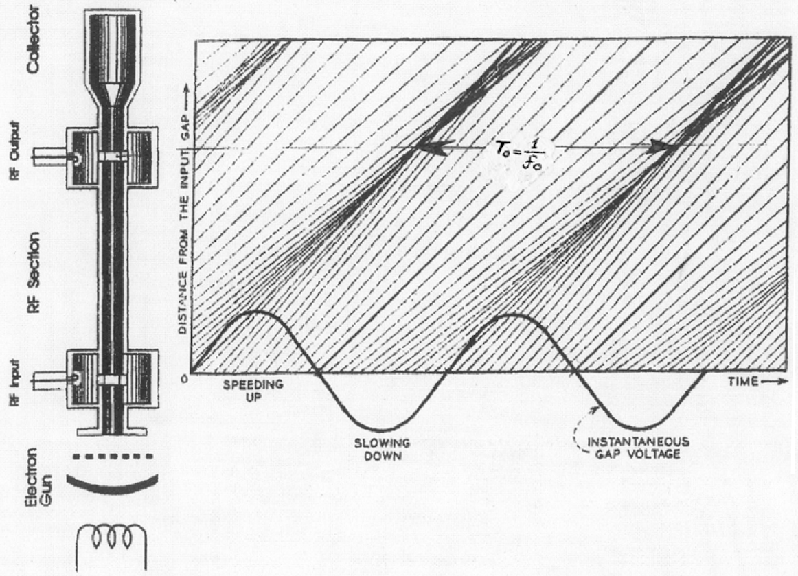 An Applegate diagram illustrating the bunching of electrons caused by the velocity modulation effect of a klystron on a number of representative electrons (24 per cycle). Each slanting line represents a plot of an individual electron’s distance over time. The slope of each trajectory is proportional to each electron’s velocity. Each electron is given a slightly different velocity as it passes through the gap between the input cavity’s grids based on the instantaneous voltage across the gap. Faster electrons catch up to slower ones, and vice versa, forming electron bunches as they drift toward the output cavity. The period, T0, of the oscillating sinusoidal RF input voltage corresponds to the duration of time between the arrival of each electron bunch at the output cavity. Source: George Caryotakis, Stanford Linear Accelerator Center from Applegate diagram by Gewartowski, J. W., H. A. Watson, Principles of Electron Tubes (Click image to enlarge)
Theory
In order to formulate the equations that govern klystron design, scientists analyze the physical principles that enable klystron operation. The simplest treatment is a kinematic theory of electron velocity modulation. Kinematic theory says that energy transfer occurs due to the ballistic motion of electrons and bases calculations on fields in the resonator cavities.
Space-charge theory improves upon kinematic theory by considering the effect of space charge. Space charge concerns self-fields produced by the electron beam itself. These self-fields, which depend on charge distribution within the beam, are distinct from the external fields acting on the electron beam but act to perturb those fields. Space-charge theory is necessary for accurate analysis of multicavity klystrons.
An additional consideration in the analysis of klystrons are relativistic effects. These effects are particularly important for high-power klystrons powering accelerators with beam voltages in excess of 50 kV. For these applications, a relativistic correction factor is applied to adjust the relevant quantities (i.e., perveance, Brillouin field, DC beam velocity, coupling coefficient, beam loading conductance, plasma frequency and plasma propagation factor). The relativistic correction factor (σ) includes the ratio of the velocity of the electron beam (u0) to the speed of light (c):
 .
.
Resources
Caryotakis, G. “High Power Klystrons: Theory and Practice at the Stanford Linear Accelerator Center.” 2004, doi:10.2172/839705. [PDF]
Watson, A., and J. W. Gewartewski. Principles of Electron Tubes, Chapter 9: Klystrons. Van Nostrand, 1965. [PDF]
Varian, R. U.S. Patent 2,242,275, Electrical Translating System and Method. Application filed October 11, 1937. Granted May 20, 1941.


