Micro Grids Can Solve Macro Problems—Part 2
Ed Brown | June 16, 2015Part 1 of this series established a case for building a system of microgrids. This article addresses some of the problems that have to be dealt with in order for microgrids to effectively address power delivery problems on a macro scale.
An International Electrotechnical Commission (IEC) white paper published in 2014 says that while microgrid technologies hold “great promise” as a transition path to low-emissions electricity networks, and as a way of improving the reliability or resurrection of supply during disasters, a number of fundamental challenges—both technical and non-technical—must be addressed before they can become commonplace.
The technical problems may be broken down into two broad categories: (1) issues around connecting microgrids to the utility grid, and (2) issues around combining different generation sources and loads within what is known as an islanded microgrid.
 New York City suffered blackouts after Hurricane Sandy hit in 2012. Microgrids can help reduce vulnerabilities to such outages. Image source: Wikimedia If a microgrid can run independently without being connected to the utility grid, it is referred to as being “islanded.” If it is connected to the utility grid, there must be a means to disconnect from and reconnect to it. If a fault occurs on the microgrid that is bad enough to cause a problem for the utility, then the microgrid must quickly trip offline. This is called “unintentional islanding” and requires the microgrid to completely disconnect from the larger grid in the shortest possible time.
“Intentional islanding” occurs when the microgrid either is automatically or manually disconnected in order to reduce the load on the main grid. An islanded microgrid can also intentionally connect to the grid during periods of reduced load so it can sell any excess energy to the utility.
When connecting and disconnecting the microgrid, challenges for both the utility and the microgrid operator include maintaining frequency and voltage regulation and coordinating the operation of protective relays and reclosers, according to a 2013 handbook from Lawrence Berkeley National Laboratory.
The definition of critical vs. non-critical loads is an important factor to consider when designing the microgrid. One rule of thumb is that the distributed generation must be able to maintain generation of 120% of the steady state load, according to William Moran, who writes in a 2015 issue of Electric Light & Power.
While the microgrid is connected to the utility grid, it is the utility grid that dominates in terms of maintaining voltage, frequency and the ability to feed inductive loads (also known as “lagging power factor”). This is because the utility grid can be viewed as a stiff infinite bus whose voltage and frequency cannot be affected by the microgrid, says Justin Jurek of Piller Power Systems, who spoke at an industry conference earlier in 2015. When the microgrid separates from the main grid, however, it has to accomplish the stabilization on its own. This means that at the moment of disconnection, a number of changes have to occur within a matter of milliseconds so as not to disturb loads on the microgrid. When the microgrid reconnects, it has to readjust just as rapidly.
Intentionally Islanded Mode
When operating in islanded mode, frequency control, voltage control and protection become necessary functions of the microgrid. Since typical loads on the power distribution system are designed to operate from 50 or 60 Hz, the source frequency on the local grid must be held within narrow limits or users’ equipment might be damaged. Electronic loads are especially sensitive and might be damaged if the frequency strays too far; what is more, inductive loads such as motors and transformers could overheat.
The same sorts of problems exist for excess voltage variations. If the generators are not designed to handle the loads’ power requirements, including reactive surges drawn by inductive loads such as motors or transformers, the voltage can drop to an unacceptably low level when the maximum load comes online. Most electrical devices are designed to operate within a specified range of variation, typically no more than +/-15%.
While there are a variety of distributed primary energy sources such as solar, wind, water and biomass, there are essentially three types of generators that feed the microgrid: induction generators, synchronous generators and inverters. Induction generators are not typically used on islanded grids because they need an external source of excitation current in order to start up—in other words they cannot execute a “black start” without help from external power.
Synchronous Generators
Synchronous generators for use on microgrids are usually powered by diesel or internal combustion engines, or by a combined heat and power (CHP) system, also known as cogeneration.
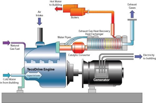 Schematic of a cogeneration system. Image source: U.S. Environmental Protection Agency. The frequency of the synchronous generator output is determined by its speed of rotation. Its output voltage is determined by the amount of excitation current in its rotor windings. Because the speed of the prime mover driving the generator can be held constant, the frequency is constant, but the output voltage can vary up and down if it is not regulated. If the generator voltage is higher than the microgrid, it will have a lagging power factor. If it is lower, then it will have a leading power factor. In both cases, the greater the difference between the synchronous output voltage and the grid voltage, the lower the power factor. The lower the power factor, the higher the ratio of reactive to real power (noted as VAR/VA). This means that a smaller percentage of power is available to feed the loads.
The high reactive currents not only do no work, but they produce I2R losses on the power lines. If there are two synchronous generators on the same microgrid whose voltage outputs deviate from the grid, there will be circulating currents between them. These currents will cause additional energy loss and overheating of the generator windings.
In a small microgrid distribution system, because the rating of each generator is comparable to the size of the individual loads, the loss of even a single load causes significant changes that the system must respond to. In particular, the distributed generators must respond to load changes by meeting the rapidly changed demand instead of tripping and disconnecting from the system.
Inverters
In order for a direct current (DC) source such as solar photovoltaic (PV) to contribute to the microgrid, its output must be converted from DC to alternating current (AC) by electronic inverters. Inverters are essentially oscillators that use power semiconductors to produce a bidirectional waveform, and then either output the AC as a square wave or filter it to produce a pure sine wave. Although some loads can function perfectly well with a square wave input, a microgrid should be able to drive a mix of loads. In order to do so, it should produce as pure a sine wave as possible to minimize currents at higher-order harmonics that could disturb other sources and loads on the grid.
Inverters also typically include protective electronic circuitry, which limit their output current so as not to exceed their rated capacity. A disadvantage is that because they cannot supply reactive power surges (such as those caused by a motor starting or a transformer connecting), there has to be a control system to prevent them from tripping offline during load spikes. Such a trip could cause instability on the microgrid.
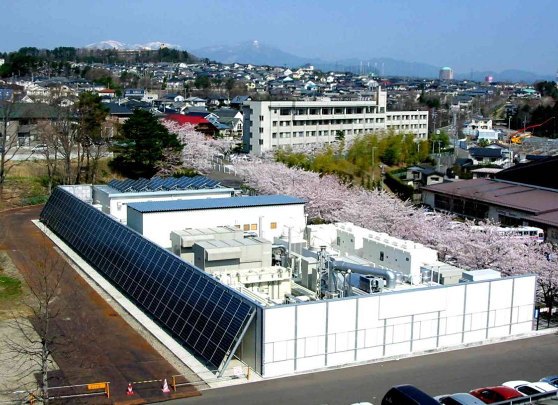 The Sendai microgrid on the campus of Tohoku Fukushi University in Sendai City in the Tohoku district of Japan. Image source: Lawrence Berkeley National Laboratory. Microgrid inverters have to be designed with the end-use application in mind. If it is intended that the microgrid will operate connected to the utility grid, then the inverter must be able to synchronize its output voltage and frequency to the grid as well as to self-regulate its voltage and frequency when it is islanded. Some inverters are designed to operate in either connection. In that case, either there must be a switch to disconnect the inverter’s grid-connection when it is being islanded, or it must be designed to allow for both modes of operation. The advantage of enabling an inverter to be permanently tied to the utility grid is that, it enables the microgrid to sell excess power back to the utility.
Protection
The microgrid protection system must “quickly remove from service any component of the system that starts to operate in an abnormal manner,” according to a 2012 article in the Journal of Applied Sciences.
Coordinating protective devices—circuit breakers, fuses, and/or relays—in a microgrid is of major importance. This requires careful analysis of both trip times and levels that are required in order to respond to different fault conditions. The aim of this coordination is to minimize disruption to both the microgrid and the utility grid by quickly isolating the two in the event of a major fault. The protective device must protect the individual generators on the microgrid, especially inverters, by quickly isolating the fault. If a fault occurs within the microgrid, the protection system is “required to isolate the smallest possible faulted section of the microgrid to eliminate the fault,” the journal article states.
One difficulty for system protection is that current can flow into the microgrid from the utility grid and back to the utility from the microgrid itself. To locate the fault, therefore, it becomes necessary to know the direction of the current flow.
Because inverters supply less fault current than synchronous generators, it might be difficult to detect a fault that is only slightly higher than the normal operating current. An example of the importance of coordinating the response times of protective devices is if there is a short circuit to ground, the fault current might decay below the device tip point before the protection has a chance to respond. Coordination of both trip point and response time must ensure that the protection closest to the fault operates first before any backup protection.
Another problem is that a healthy feeder might disconnect from the grid because it is sending current to a short circuit in an adjoining feeder. Utility power grids are designed to automatically restart after a short duration fault such as a lightening strike. A grid-connected microgrid must be able to ride through such so-called “transient conditions” so as not to destabilize either itself or the main grid (this is known as low voltage ride through or LVRT).
During a faulted shutdown on the utility grid, the microgrid must automatically disconnect from the utility grid so there will be no chance of backfed power that could injure linemen, for example, who are working to repair downed power lines.
Power Quality
Nonlinear loads cause distorted current waveforms rich in harmonics that impinge on all of the generators that are attempting to supply a pure 50 or 60 Hz output. The harmonics are produced when current is drawn for only a portion of the applied sine wave. The major culprits here are switch-mode power supplies (which actually have circuitry similar to that used by inverters). These power supplies are used in computers, servers and microwave ovens, for example.
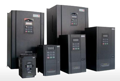 Variable frequency drives represent another class of nonlinear load. Image source: vfds.com. Another class of nonlinear load is electronic power controllers, such as variable frequency motor drives (VFDs) and electronic light dimmers. Yet another is electronic lighting ballasts used for fluorescent lighting. A single one of these loads will not have much effect, but their use is expanding as more applications for computers are developed, as more data is stored and as variable power controllers are added to reduce energy consumption. The result is that there are typically large numbers of these types of load on a single grid.
Some of the power distribution problems caused by nonlinear loads have been addressed in the National Electrical Code. These include the possibility of additive odd harmonics, which can cause current flow on the neutral of a three-phase system of up to 1.73 times the balanced phase current. This not only could cause the neutral connector to overheat, but also lead to excessive heating of transformers.
Connection and Disconnection
When transitioning between grid-connected and non-connected operation, it is critical that voltage disturbances are quickly damped and that the appropriate adjustments to the protection systems are automatically applied. If the microgrid is unintentionally islanded, it must have enough capacity to feed the total load. If not, there has to be a means of automatically shedding non-critical loads. Before reconnecting, the voltage amplitude, frequency and power factor on the microgrid side must synchronize with that of the main grid.
Although there is growing consensus about the usefulness of microgrids to enable incorporating renewable energy resources and providing a means to mitigate problems such as blackouts and power demand peaks, agreement also exists that, in the words of the Lawrence Berkeley handbook, “the merging of renewable energy microgrids with regional or national power grids calls for standardized best practices and technologies to ensure safety, efficiency, reliability, and best value for mini-grid operators, utilities, and their customers.”
In the U.S., IEEE 1547 and UL 741 are being expanded to address these issues. Abroad, the IEC white paper concurs that “there is currently no uniformly accepted standard that helps to understand how microgrids behave or interact with the wider electricity system.”


