
Wind Farms Are Not as Efficient as You Might Think
Siobhan Treacy | October 04, 2018University of California Santa Barbara researchers have found that wind farms aren't reaching their full efficiency potential. As a result, they have proposed some solutions for this problem.
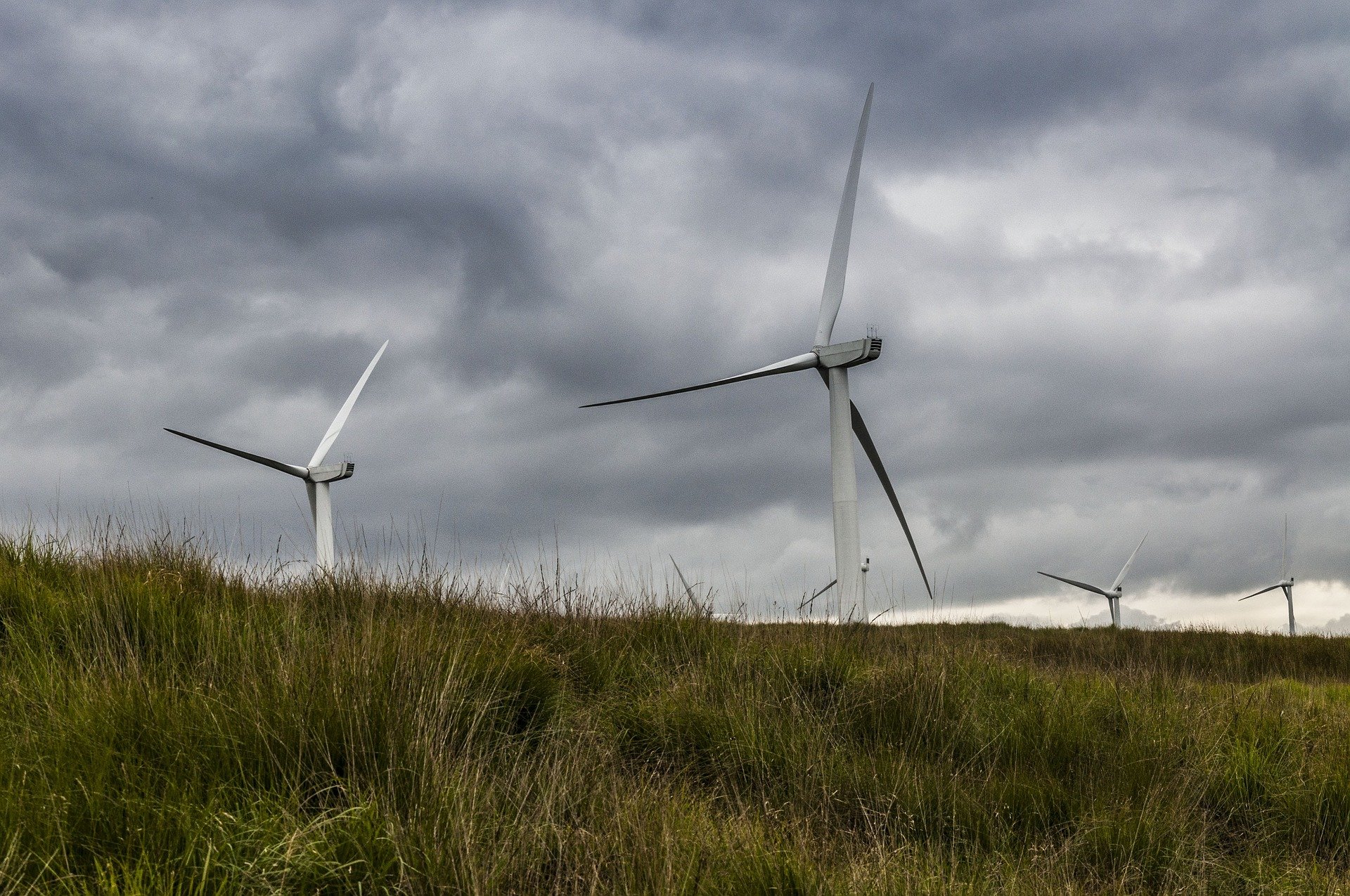
“We've been designing turbines for use by themselves, but we almost never use them by themselves anymore," said UC Santa Barbara mechanical engineering professor Paolo Luzzatto-Fegiz.
When wind energy first entered the efficient energy scene, a wind farm consisted of one or just a few wind turbines. But today's wind farms can have hundreds of turbines. When turbines are placed close to each other, they block each other from reaching the highest-power wind. The turbines at the back of the group receive weaker wind than the turbines at the front.
"These turbines are now very good at extracting power from wind, but they also form these very big wind shadows," said Luzzatto-Fegiz. "So, you can see that it's not a matter of packing more turbines on your piece of land, because at some point you hit these diminishing returns. There's a point where if you keep adding turbines the amount of power you get becomes less."
The ultimate goal is to provide all wind turbines with the highest-velocity wind possible. The wind above the turbine is much faster than the wind below the turbines. Mixing the airflow in the wake of the turbines with the untapped air above could be one fix to the efficiency challenge.
"If you could somehow invent a gadget that for each of these turbines causes these wakes to mix very quickly, you can potentially have these huge improvements," Luzzatto-Fegiz said.
Another solution would be using a turbine with blades that rotate on a vertical axis, rather than the more-common horizontal-axis turbines.
"These don't perform as well ordinarily by themselves, but it's significant that they essentially can cause much stronger mixing in their wakes," Luzzatto-Fegiz said about vertical-axis turbines. "...and people have shown that if you put them in an arrangement where they spin in opposite directions to each other they can cause very nice mixing."
Creating more efficient winds farms doesn’t just create more wind. If a wind farm is at maximum efficiency, it requires fewer wind turbines and lowers the overall cost of a wind farm.
The paper on this research was published in Physical Review Fluids.


These are all good points. But, I'm still having trouble understanding why even a single turbine is considered worthwhile as designed. It seems to me that the blades are only a few percent of the surface area available to harvest the wind. Why are there not more blades on that single turbine to "collect" the wind? Seems like 95% of the wind just passes by without being used. What's up with that? I still don't get it.
In reply to #1
What you say would be true if the windmill is not turning. When it is turning, each point on each blade traces out a helix, so the blades are really intercepting more air, like an airplane wing flying through the air.
For any given windspeed, there are curves of available torque versus turbine speed. The maximum point on each curve (highest torque) is the speed at which the turbine blade intercepts the air at the best angle of attack.
Depending on the electrical load, there is a load line that plots needed torque versus rpm. Where this load line intercepts the available torque versus turbine speed is the resulting operating point as shown in the diagram below.
It can be proven mathematically that a maximum of 59 percent (or 16/27) of the kinetic energy of the moving air can be captured, known as the Betz limit.
https://en.wikipedia
In reply to #2
Okay. I get that. But, ".... of the moving air can be captured...." begs the question, "Which moving air?". To me, the only relevant moving air is the air that actually hits the blades. 59 percent of what? The more surface area, the larger that 59 percent becomes because it's 59 percent of a larger number.
Once the blade moves from one position to another, it's now collecting air energy from a different stream of air (which didn't hit the blade before it changed its position). Now, the stream that used to hit the blade misses it, while the new stream does hit it. I don't think you can treat the whole circular area as one single stream, but as a flux of many individual streams. And, only a given number of those individual streams can be hitting the blade at the same time, unless you increase it by increasing the surface area of the blades. Then, that 59 percent becomes 59 percent of a larger number. Which when combined, increases the air energy collected by the turbine, which increases its output capacity (unless limited by some other factor).
In reply to #3
Consider the area the rotor blades sweep in a revolution, the rotor disk. A mass of air, m, moves through this disk in 1 sec at velocity v. The total kinetic energy of this packet of air is (1/2)mv2 , if the air were to be brought to a stop. But the air cannot be completely stopped, it has to move out of the way for more air to enter, so it must still retain some velocity. This is where Betz limit comes in, it's the best that can be achieved.
If the turbine is turning, the blade interacts with the airstream, removing some of the air's momentum, slowing that air down. As it turns, it interacts with "new air", capturing its momentum and so on. So it is really sweeping the rotor disk capturing as much momentum as possible.
In reply to #3
I fear that I didn't give the best answer to your question. Windmills seen on old farms used to pump water have many wide blades. In a slight wind, there is enough torque produced for them to turn. Wide blades produce more torque for a given wind speed but at a slow rpm. But Power = torque x rpm, and these windmills are not very efficient but do supply sufficient torque to turn a water pump.
Power station blades are long and thin airfoils. Long and thin airfoils are very efficient, having a high lift/drag ratio, and are used on glider planes where the glide angle is very small. The analogy of a glider plane to a windmill blade is that the loss in altitude represents wind speed and forward motion of the glider represents rotor blade speed. Rotor tip speed on 3 blade wind turbines are typically 6-7 times the wind speed. (As an added bonus, high speed is also preferable in that a lesser gear ratio is needed to drive the generator.)
Energy is not lost by wind blowing between the blades. Rather, the blades fly through the wind in a spiral pattern as shown in the diagram below.
From a simulation run on the Yellowstone supercomputer, these contour lines and isosurfaces provide valuable information about turbulence and aerodynamic drag in this visualization of air flow through the blades of a wind turbine. (Image courtesy of Dimitri Mavriplis, University of Wyoming)
https://www2.cisl.uc
In reply to #5
That's interesting. But, I don't think I can properly understand it without an animated version of that diagram. I don't know what to make of those red "velocity loops" at the top of the diagram. There's no corresponding representation at the current position of the blade tips when this "snapshot" was taken to trace into those spiral traces. I'm not sure what that means. Seems to me, whatever turbulence occurring at the tips of the blades would also follow the same spiral pattern as the blades themselves. I see no spiral pattern represented in those velocity lines. Therefore, I can't relate them to the blades. An animation would show how the wind velocity would change with the path of the blades (which has a spiral pattern).
Also, there are two legends with the same color code. How to tell which is which? What's P/Pinf? Is that some pressure ratio? It needs a different color code to avoid confusion. Maybe those red "velocity loops" are really pressure points (which should also follow the same spiral pattern as the blades. I get what they're trying to explain, But I can't really read it. I think I need an animation.
This is food for thought, tho. Thanks.
In reply to #6
I agree with you, this picture doesn't look right. I searched for a picture to illustrate my point and referenced where it came from. I've looked some more, and I think it originated at this site:
https://www.rdmag.co
This link is about a supercomputer and the windmill is an example of a simulation run on it. It's almost like the simulation is upside-down. I would expect to see the vortices shown in red at the top to be at the bottom instead, where the blades pass by the base. More likely, the simulation includes an obstruction at the top that doesn't match the picture.
Pinf, I believe is the pressure at a distance away from the influence of the windmill, so P/Pinf is pressure ratio from ambient.
So, this is tnot a good example...
Here is an animation that shows the startup in a constant wind. Once it is up to speed, it is capturing the momentum from the air through the whole disk. The inefficiency of an airfoil is the shed vortices at the blade tips, which produce "induced drag". This is the reason long thin blades are more efficient.
https://www.youtube.
In reply to #7
That was much better. I think the key is "Rotor tip speed on 3 blade wind turbines are typically 6-7 times the wind speed". At that speed, it doesn't give the "used air" that much time to "get out of the way". Definitely a significant factor.
Thanks.