The Proving Ring: How Innovation Led to a Simple Tool to Verify Weight
Bill Schweber | May 19, 2015 Every engineer who uses instrumentation for test and measurement eventually faces the question: "How do I know if my results are really what the readout says they are?"
Some sort of calibration or independent confirmation is needed to verify that a sensor and its associated front-end electronics are providing accurate, consistent signals and resultant data.
To check time or distance, traceable standards are available at modest cost to be used as calibrators, including an atomic clock for time and a light-wavelength system for length. However, for checking weight such as applied to a scale or load cell, there are no reproducible secondary standards. Therefore, engineers frequently resort to deadweights, which are traceable back to the National Institute of Standards and Technology (NIST) or an equivalent standards organization. The unit of weight and force is stated as newtons in the SI system, but more often is dimensioned as mass, in kilograms, or as pound-force in the non-metric world. More typically, the measure is called either a pound or a kilogram.
(To learn more about using units of mass rather than weight and force, click here.)
Logistics Headache
In principle, it shouldn't be difficult to buy some weights for calibration and leave them in a cabinet until needed. In practice, however, it is a very big deal, especially as the weights needed rise into the hundreds, thousands, tens of thousands of pounds, and perhaps even more. The problems become obvious because moving these so-called “proof weights” is a major logistic headache. What's more, attaching them to the measuring sensor and system under test is a technical challenge, and they take up considerable space even when not in use.
Fortunately, there is a better approach: namely, that of using a proving ring as the solution to the dilemma of verifying weight and force. This ring is a conceptually simple weighting simulator and readout. It was developed in the 1920s at the U.S. National Bureau of Standards (NBS, the predecessor of NIST).
The proving ring is a metal ring which flexes under an applied load. If fabricated properly, the ring's diameter will change with a consistent, reliable, linear relationship of load versus deflection. The ring's deflection spans bidirectional use, stretching for tension loading and shrinking for compression loading. As a result of the load -versus-deflection characteristic, it provides precise equivalent of deadweight calibration indication, but at a fraction of the size, cost and weight.
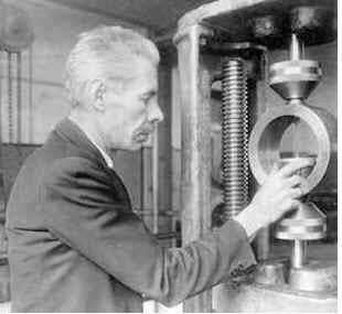 Serge Petrenko was trying to resolve inconsistencies in the results of the Brinell hardness test and hit upon proving rings. Source: NISTAs with so many technology advances, the developers of the proving ring did not start with the goal of developing a replacement for deadweight calibration. Herbert Lucius Whittemore, head of the NBS Engineering Mechanics Section, and Serge Nicolas Petrenko, an engineer in the section, were trying to resolve inconsistencies in the results of the Brinell hardness test. In this test, a pressure gauge pushes a plunger with a ball tip at a known force into the sample under test. The diameter of the resultant indentation, which is much easier to measure accurately than its depth, is a quantitative indication of the sample's hardness.
Whittemore and Petrenko found that their Brinell results were inconsistent, largely due to problems with the accuracy of pressure gauge and hydraulic pump used to impress the plunger. Using deadweights gave much better results but was impractical, especially at non-NBS locations. The two came up with the idea of adopting the deflection of rings under load, and received their first patent in 1926.
How It Works
The principle behind the ring's deflection is well known to mechanical engineers. In simplest form, for a thin ring under modest compression (or tension) of load P, the decrease (or increase) in ring diameter is proportional to PD3/EI, where D is the diameter of the ring, E is the modulus of elasticity of the ring's material, and I is the dependent on the ring's cross section. Thus, for small loads, the deflection is linearly related to applied load. A detailed analysis provides a more complicated and precise equation that takes into account various second-order factors (see reference 1, below), but the linear relationship remains valid.
Since proving rings operate with fairly small deflection to stay within their linear range, measuring the miniscule deflection of the ring (typically between 0.05 to 0.10 inch under full load for a medium-sized unit) requires a unique, non-obvious approach. This is done using a vibrating reed mounted within the ring on a special micrometer screw mechanism and small button opposite the free end of the reed. (See the accompanying schematic.) The reed is manually or electrically tapped to start it vibrating; as the ring deflects, the micrometer is adjusted until the reed's tip grazes the button and the reed's sound changes dramatically; then the micrometer position can be read. Though this technique may seem almost archaic, it provides repeatable and consistent indications – the hallmarks of good metrology – with accuracy to about 0.00005 inch. Newer proving ring systems also use a video camera and image-measurement software to measure the ring's deflected size.
As with most instrumentation, squeezing that last bit of precision performance requires care in design and fabrication, even if the underlying principle is simple. Construction of a proving ring starts with an annealed, forged ring made of special steel alloys, which is then precision-ground to final size. The threaded attachment bosses which connect to ring to the rest of the system are not welded on, as this would introduce uneven stresses and subsequent errors; instead, they are part of the original forged shape although they complicate the forging. (There are slight differences in the design of these attachment points with proving rings intended for solely for compression use versus those only for tension.)
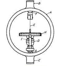 Schematic of a compression proving ring (A) where (B) and (C) are external bosses for attachment and (F) and (G) are internal bosses; (D), (H), and (I) form the precision deflection-measuring micrometer; and (E) is the vibrating reed. Source: NISTProving rings do not drift or change with age so long as they are not use beyond their deflection limits; many have been in use for decades. For highest accuracy, a proving ring needs to be used at a specific temperature (or else a correction factor must be applied), since all metals have a temperature coefficient of expansion which affects their size. A proving ring can be calibrated by NIST or in-house deadweights, and then used in the field at other locations, solving the on-site weight/force calibration challenge.
Cost-effective and Practical
When used properly, a proving ring provides absolute accuracy of between 0.0125% and 0.075% of reading, according to Morehouse Instrument Co. Inc., one of the leading suppliers of this precise secondary standard. Morehouse Machine Co. was founded in 1920 by William S. Morehouse and became known for its ability to manufacture precision parts due in large part to the machining skills of Harry E. Zumbrun.
Morehouse Inc. says that a ring rated for 1,000 pounds measures from 6-12 inches in diameter, is about 1-inch thick and 2-inches deep, weighs under 10 pounds, and sells for less than $5,000; one with a 300,0000-pound rating is less than 20 inches in diameter, weighs about 150 pounds, and costs around $20,000. All of these values are far less than their deadweight equivalents. As an added benefit, multiple smaller proving rings can be used in parallel to reach higher ranges, if needed.
Simulation and replication of key physical standards are ongoing challenges spanning accuracy, precision, dynamic range, and other factors. Innovations such as the proving ring demonstrate that the impetus for advances in one application – here, the Brinell hardness test – is often the driver for innovation in other areas.
References:
1. "Proving Rings for Calibrating Testing Machines," Bruce R. Wilson, Douglas R. Tate, and George Borkowski, National Bureau of Standards, 1946.
2. http://www.nist.gov/pml/div684/grp07/provingring.cfm
3. http://www.mhforce.com/products/proving-rings
4. "World in the balance: the historic quest for an absolute system of measurement," Robert P. Crease, W.W. Norton, 2011.