Rethinking the Centrifugal Fan Selection
May 21, 2018Sponsored story
The centrifugal fan is one of the most prevalent fan types used in the HVAC industry today. Two main categories of centrifugal fans are those that use impellers with forward curved (FC) blades and those that use impellers with backward curved (BC) blades. Each category is descriptive of the direction of the blade curvature relative to the direction of the impeller rotation.
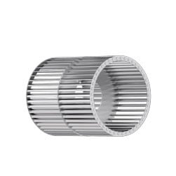 Figure 1: Example of squirrel cage type FC centrifugal impeller. Source: ebm-papst Inc.A very common type of centrifugal fan, typically referred to as a centrifugal blower, uses a squirrel cage type wheel with many FC blades (Figure 1). The blades are shallow with a substantial curvature in the direction of rotation that results in a higher blade tip speed than a BC blade. This means the impeller can move a large volume of air at a relatively low speed in a small footprint, providing advantages in acoustic noise and size reduction. Combining these advantages with an inexpensive lightweight construction has led to FC centrifugal blowers to being the default choice for many lower pressure HVAC applications such as residential furnaces, central station air handling units and packaged rooftop air conditioners. While they are often the favored option, there are additional factors to consider.
FC Impeller Considerations
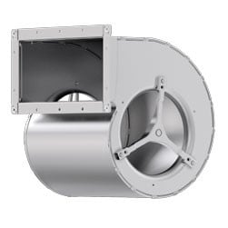 Figure 2: FC centrifugal blower scroll housing. Source: ebm-papst Inc.A substantial portion of the total energy of the air leaving an FC centrifugal blower is in the form of velocity pressure. A scroll housing (Figure 2) is required to convert that velocity pressure into usable static pressure that can move air against the system resistance present in the application. Completing this conversion in the most efficient manner requires an outlet duct of the same size as the fan outlet and of sufficient straight length to allow a uniform air velocity to develop across the duct. These housing and duct requirements diminish the advantage of the compact impeller size.
A second challenge lies with the performance and power curves of an FC impeller (Figure 3). To the right of the peak efficiency operating point, the power curve rises steeply and continuously with lower system resistance. Operation in this area could overtax the blower motor. To the left of the peak efficiency operating point, the performance curve can dip noticeably, creating an area where the fan may stall or hunt between similar system resistance points. This can result in system pulsations that generate noise or even damage the blower or ducting if a system resonance condition occurs.
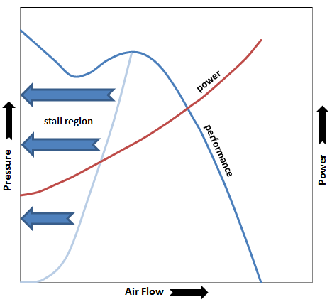 Figure 3: Characteristic curves of an FC centrifugal blower. Source: ebm-papst Inc.Additionally, the comparatively low FC impeller efficiency is further degraded by the commonly used arrangement of an induction motor driving the blower wheel through a V-belt and sheaves (Figure 4), with the motor speed controlled using a variable frequency drive (VFD). As cited by the Department of Energy’s
 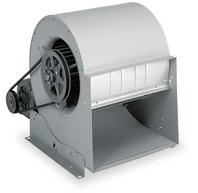 Figure 4: Typical FC centrifugal blower with a V-belt and sheaves setup.Advanced Manufacturing Office, smaller horsepower VFDs operating at full load and newly installed V-belt drives perform with typical peak efficiency levels of 95 percent. Improperly installed or maintained belt drives can quickly lose efficiency, while part-load operation can substantially decrease the efficiency of both the VFD and drive motor. A VFD may require filters for EMI/RFI, a supply voltage for an external sensor, a motor protection switch, shielded cables, filters to prevent common mode currents from damaging the motor bearings, or use of an inverter-duty rated induction motor, all of which can increase upfront or maintenance costs.
Assessing these factors during selection of a blower, especially if the operating point is not well known or is variable, may lead to a better option that simplifies installation, saves energy and lowers future maintenance costs.
Backward Curved Impeller Considerations
BC impellers have deep blades with a long cord length that provides efficient expansion of the airflow within the blade passages (Figure 5). This means conversion of the velocity pressure to static pressure with a uniform velocity distribution occurs prior to the air exiting the blower, eliminating the scroll housing and lengthy outlet duct requirements of an FC impeller.
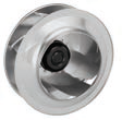 Figure 5: Backward curved centrifugal impeller. Source: ebm-papst Inc.BC impellers also offer more forgiving performance and power curves. They provide greater efficiency across the entire speed range, a non-overloading power curve at reduced system resistance and no substantial dip at the higher end of the pressure curve that could result in hunting or stall conditions.
The favorable power and performance curves allow BC centrifugal blowers to serve as a viable alternative in applications where FC centrifugal blowers are traditionally used, such as in packaged rooftop air conditioners. This is especially true when they operate over a variable speed range or when higher system resistances are involved.
ebm-papst RadiPac EC Centrifugal Fans
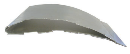 Figure 6: Airfoil blade. Source: ebm-papst Inc.
An even more aerodynamically efficient and acoustically improved subset of the BC impeller uses an airfoil blade. These blades are hollow and shaped like an airplane wing to decrease weight and drag (Figure 6).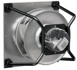 Figure 7: RadiPac centrifugal fan. Source: ebm-papst Inc.
ebm-papst offers BC airfoil impellers in their RadiPac centrifugal fans (Figure 7). The “Pac” in RadiPac is short for packaged, as all required control and sensing functions are bundled into the fan assembly. The BC airfoil impellers are combined with high-efficiency, direct-drive GreenTech EC external rotor motors. Under the right circumstances, this combination can substantially reduce power and space requirements when compared to the classic VFD controlled, shafted induction motor and belt driven FC impellers. RadiPac eliminates the need for ancillary components that are common with these traditional systems (Figure 8).
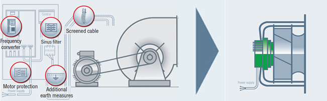 Figure 8: Common FC centrifugal blower and drive arrangement versus RadiPac BC centrifugal module with integrated EC external rotor motor. Source: ebm-papst Inc.
Comparison Testing
RadiPac and FC centrifugal blower airflow and power measurements were made in an air test chamber that meets AMCA 205 and ISO 5801 requirements. Input power comparisons are shown (Figure 9) at two matching operating points along the FC blower air performance curve — OP1 (Operating Point 1) with the RadiPac running at full speed and OP2 (Operating Point 2) with the RadiPac speed reduced to 88 percent of full speed. As indicated by the green arrows, these operating points represent potential RadiPac power savings of 21.5 percent and 28.6 percent, respectively.
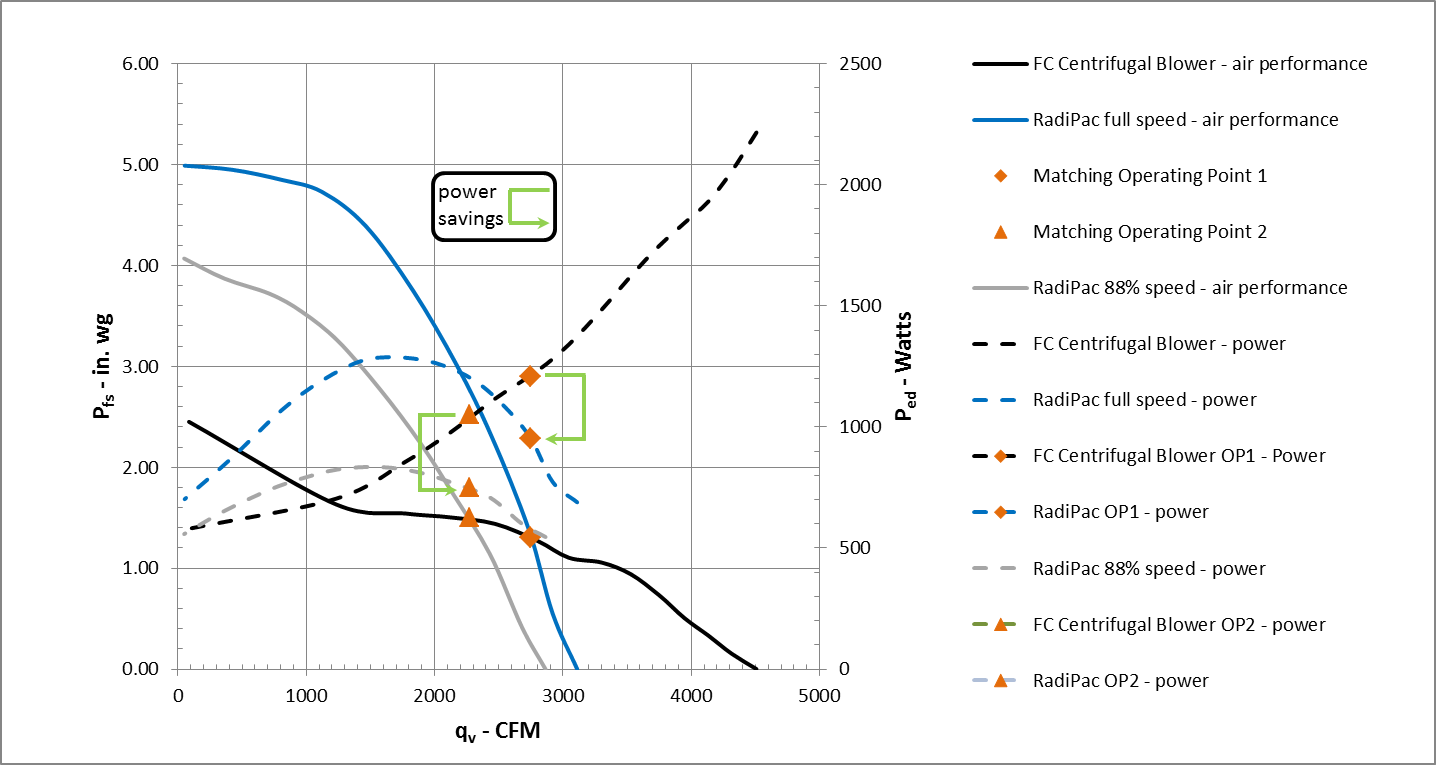 Figure 9: Potential power savings when replacing an induction motor and V-belt driven FC centrifugal blower with a RadiPac EC centrifugal fan. Source: ebm-papst Inc.
Beyond the Power
RadiPac modules offer many benefits beyond the power savings, including:
- An external rotor motor design (Figure 10) positions the spinning rotor onto the outside of the stator instead of the reverse as on standard internal rotor induction motors. Mounting the impeller directly onto the rotor shell creates a very compact unit that allows dynamic balancing of the entire rotating assembly, reducing vibration and prolonging bearing life.
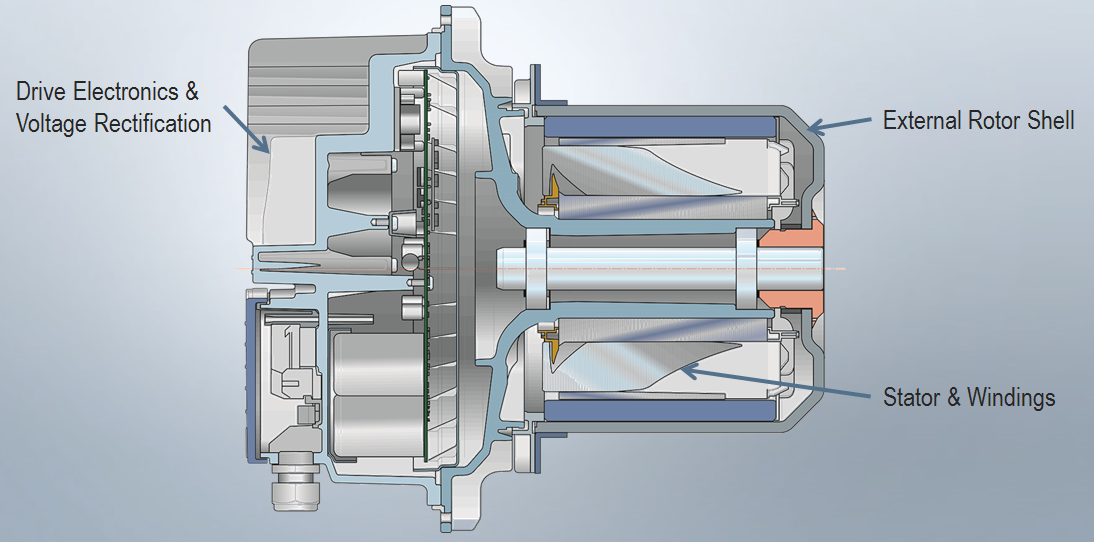 Figure 10: External rotor motor. Source: ebm-papst Inc.
- Integrated electronics for commutation and control replace the external VFD and eliminate the need for ancillary components to provide grounding or shielding measures. The electronics and motor form one unit and are perfectly matched to one another, eliminating labor-intensive adjustments before commissioning.
- Internal monitoring functions of a RadiPac EC motor are easily accessed in the application, providing feedback including error codes, motor life, motor temperature and speed. RadiPac fans also come standard with other beneficial features including soft start, locked rotor protection, current limitation, thermal overload protection, undervoltage detection, phase failure detection, a status relay and an RS485 MODBUS-RTU interface for bus communication.
Conclusion
When properly applied, ebm-papst RadiPac EC centrifugal fans can provide significant advantages over traditional VFD-controlled, belt-driven FC centrifugal blowers in many applications. The aerodynamic efficiency of an airfoil impeller driven by modern GreenTech EC motors achieves high operating efficiencies even under extreme part-load conditions. A host of standard control, monitoring and safety features adds to the value of the package. Design engineers are presented with an attractive alternative for FC centrifugal blowers that can substantially reduce power and space requirements.


"The blades are shallow with a substantial curvature in the direction of rotation that results in a higher blade tip speed than a BC blade."
This doesn't make sense. With the same RPM and the same radius, the blade tip speed would be the same for FC or BC.
In reply to #1
Thanks for the comment John and you're right. This could have been clearer. It's the air velocity that is different.
V1 = tip (tangential) velocity; V2 = radial velocity; R = resultant velocity
FC = resultant air velocity “R” leaving the blade is greater than the blade tip velocity
BC = resultant air velocity “R” leaving the blade is less than the blade tip velocity
Fan performance tables are based on standard air. Selecting a fan using standard tables will provide a fan capable of moving the required flow and developing the required pressure. As the temperature increases and humidity decreases, system resistance and the pressure developed by the fan will decrease at the same rate, and a constant flow rate is maintained. Altitude reduces the air pressure and density along with the amount of moisture the air can carry. The density and moisture values in table 1 must be divided by the correction factors in table 4 to determine the actual density and mois-ture content per cubic foot.
In many dryer applications, the static pressure requirement is between 0.5 and 3" 0f water column. For these pressure requirements, a duct vaneaxial fan often is the best selection. The duct vaneaxial fan offers a broad performance range and good pressure capability at high static efficiency. It also offers the benefit of placing the bearings, shaft and drives on the negative pressure side of the propeller. This setup draws ambient air across those components during operation and discharges it into the hot moist air. This fan also can be provided with a shaft seal to further isolate the components or high temperature construction for operation up to 500 deg. F (260 deg C).
For higher pressure ranges, a backward curved centrifugal fan often is selected. This design offers pressures up to 20" water gauge. They also offer the benefit of having the shaft and bearings outside the fan, and they can be mounted on the roof with a weather cover.
As with all fan systems, it is important to remember that only available air can be exhausted. Fans cannot operate in a vacuum. If the exhausted air cannot be replaced in the facility, fan performance will drop off and production will suffer. The production facility must have makeup air for every cubic foot that is exhausted from the facility. The makeup air can be provided through general ventilation systems or as part of a heating, ventilating and air conditioning system.
With the exhaust requirements calculated and fan system sized to handle the required volume at the required pressure, the drying process will run smoothly. Production results are consistent and the production facility's environment also is improved by removing contaminated air. A good understanding of exhaust requirements allows better control of the drying process ventilating.com fanblower.com highpressureblower.n
A ventilation system should provide for a comfortable environment with respect to humidity and temperature. The overall goal of climate control is to provide an environment that is not too cold, hot, dry or humid, and that is free from drafts and odors. Humidity refers to the amount of moisture in the air and extremes in humidification levels can influence how comfortable you may be. When the air is too humid, it makes people feel uncomfortable (wet, clammy) and can promote mold growth. On the other hand, low humidity conditions (which typically occur in the winter months) dry out the nasal and respiratory passages. Low humidity may be associated with an increased susceptibility to upper respiratory infections. Static electricity problems (affecting hair and clothes, particularly synthetic fibers) are good indicators of an office with low relative humidity.
I was given an assignment to write down the working principle of Centrifugal Fan and some description about its different kinds. Click studyclerk.com to get college essay writing service online. I think I have collected a lot of helpful content from your source for which I am very thankful.