Guide to Enhancing Steam Turbine-generator Reliability
Victor Rodgers | September 22, 2016Steam turbines directly drive electric generators to produce approximately 80% of the world’s electricity.
Turning at speeds up to 3600 revolutions per minute, turbines and generators (T/G) are subject to failure. Their reliability depends upon correct operations, condition monitoring, and life extension practices. And when failures do occur, root cause identification is critical in mitigating future failures. Second only to boiler tube failures, turbine outages represent the largest contributor to unplanned unavailability.
T/G failures are responsible for millions of dollars of lost generation, plus additional millions paid by casualty insurers for replacement power. Additional costs are incurred by emergent equipment replacement expenses and part unavailability. Sometimes, generator rotors even need to be transported off-site for “spin pit” testing where imbalance issues are diagnosed.
 Blade and diaphragm degradation is a common occurrence.When failures do occur, their root cause(s) frequently go unidentified, as efforts focus toward quickly restoring the unit to service. Industry experience demonstrates that when failed rotating components are simply replaced in-kind, the responsible root cause reemerges. The financial risk of repeated turbomachinery failures far exceeds the typical investment required to identify and implement life extension strategies. The enduring consequences of most failure modes can be mitigated or prevented by enacting current technologies.
The following turbine-generator failure types highlight both the common and the catastrophic. Although not an exhaustive list, it serves to demonstrate the kinds of failures that occur frequently or with high consequence.
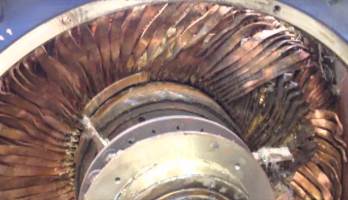
• Blade and diaphragm degradation is a common occurrence. Gradually accumulating over time, this degradation is usually identified and remedied during planned maintenance outages. When degradation exists, it frequently results in lost thermal efficiency and megawatt output reduction. Erosion issues are largely confined to the initial high-pressure turbine stages, while corrosion is common among the final (wet) stages of low-pressure rotors. Although forced outages are rare, the consequences of degradation can be acute and costly. Degradation results in inefficiency and operational range limitations caused by increased clearances, geometrical changes, and flow path surface cleanliness.
Various modes of failure cause turbine degradation. Particle accumulation on flow path surfaces can cause fouling. Steam chemistry influences corrosion or pitting which deteriorates machine internals. Solid particle impingement wears flow path surfaces through erosion. Rotating members rubbing against stationary surfaces initiate abrasion. Although some modes can be reversed through washing, others are permanent and require repair or replacement. Generator degradation manifests as rotor issues, misalignment, imbalance, eccentricity, and mechanical or electrical faults.
• Blade cracking and failures are also common. Turbine blading is designed to endure intense operating conditions. In fact, the calculated centrifugal force at the tip of each operating blade of a 500 MW low-pressure steam turbine is equivalent to approximately 200,000 lbs. or 70 Volkswagen Beetles! Many years of static, dynamic, and thermal loading take their toll. When failures occur, they can be catastrophic. A single “thrown blade” while in operation frequently can damage nearby equipment.
• Disk cracking or rupture is prominent and initiates among disk faces, bores, rim attachments and keyways. Stress corrosion cracking (SCC) has been identified as the primary root cause. The concurrent effects of material properties, transient temperatures, tensile stressors, and the steam entrained gases of oxygen and carbon dioxide contribute to SCC as demonstrated through crack initiation and propagation. Failures of disks can be catastrophic when fragments penetrate the turbine casing.
• Rotor bursts of the turbine or generator are uncommon but often catastrophic in nature. Although generator bursts are less likely to penetrate the shell, a hydrogen explosion or lube oil ignition often results in significant fire damage. Turbine rotor bursts, usually rare, produce large projectil,es which penetrate the shell and cause damage to neighboring equipment. Rotor fragments, often weighing several tons, have breached building structures and been thrown hundreds of feet.
Condition Monitoring
Historically, when turbine or generator failures occurred, the root cause(s) of failure were not determined. Subsequent repeat failures were common. Those days are gone. T/G equipment does not randomly fail. Each failure can be attributed to a root cause. Most often the failed part’s condition changed and prompted failure.
 A single “thrown blade” while in operation frequently can damage nearby equipment.Failure history knowledge and failure analysis information should be used to select critical equipment for monitoring. Accurate operational limitations and correct instrumentation needs to be selected for condition monitoring. Awareness of why components fail coupled with accurate condition monitoring is a proven method of achieving high reliability.
Life Extension
Turbine and generator equipment replacements are fast becoming cost-prohibitive. Life extension strategies are now the preferred approach. Each turbine has its own unique signature. Although most are designed to achieve at least 100,000 operational hours, their real lifetime depends more upon modes of operation, condition monitoring, and maintenance practices. Live steam conditions, operational parameters, and cycling profiles influence specific failure mechanisms which weaken particular components. These variables make it difficult for engineers to determine which actions to be taken, and when, to best ensure reliability and availability of T/G components. An effective, structured life extension strategy should extend T/G operation beyond their designed lifetime.
Turbine component lifetime primarily depends on its individual operating conditions and maintenance practices. Material creep, low cycle fatigue, and thermal aging are chief mechanisms which influence premature failure. Elevated temperatures and stress levels combine to accelerate component damages to high pressure turbine rotors, casings, valves, and steam piping. Low-pressure components are degraded by erosion, corrosion, and elevated stress.
Correct water/steam cycle chemistry is also critical. Steam impurities, such as from a condenser leak, can accelerate corrosion, influence efficiencies and cause untimely failure. Generators are, in the same way, negatively influenced by thermal, electrical, and mechanical variables which degrade efficiency, reduce output and increase general failure risk.
Regular inspections should be performed on specific components at the correct intervals. Visual inspections, non-destructive testing (NDT) and even comprehensive analyses such as finite-element based calculations may be needed. Destructive testing should be performed to examine and evaluate metallurgical abnormalities or degradation as they compare to original design and operational histories.
In short, life extension strategies should be comprehensive. All information collected among inspections and condition monitoring should be combined with operational and failure histories to formulate unique recommendations for each component. The resulting strategies, based upon rational and quantitative data, should target which parts will be replaced, repaired, re-inspected; which conditions better monitored; and which operational regimens modified, with corresponding timeframes and priorities.