Steam vs. Combined-Cycle vs. Cogeneration: Understanding the Basics
Brad Buecker, Process Specialist, Kiewit Engineering and Design Co. | August 18, 2016This article examines fundamental thermodynamics of conventional steam-based power generation as a method of explaining why combined-cycle and cogeneration power production continue to grow in popularity. Yes, environmental regulations have put the coal-fired power industry in a bind, but efficiency and economics are perhaps even greater factors in the transition to new technologies.
Thermodynamic Definitions
The word “thermodynamics” conjures up visions of complex mathematics to many people. Yet, relatively simple formulas from thermodynamics can be used explain much about steam generator basics. Consider a fundamental Rankine cycle, as exemplified by the schematic.
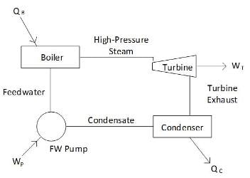 A basic steam-based power generation cycle.Heat input (QB) is of course at the boiler (and we will assume that the boiler has a superheater), work is done in the turbine (WT) to produce electricity, and waste heat is rejected in the condenser (QC). The work done by the boiler feed pump (WP) is minor compared to the other energy transfer processes, so we will ignore it for this example.
Thermodynamics is built around two laws. They are sometimes referred to as (first law), “You can’t get something for nothing,” and (second law), “You can’t break even.” In actuality, the first law is that of conservation of energy. It says that energy used within a system is neither created nor destroyed but only transferred. The classic energy equation for a simple system (defined as a control volume in textbooks)1,2 is:
Q – Ws = m2[V22/2 + gz2 + u2 + P2v2] – m1[V12/2 + gz1 + u1 + P1υ 1] + dEc.v./dt Eq. 1
Where,
Q = Heat input per unit time
Ws = Shaft work such as that done by a turbine per unit time
m2 = Mass flow out of the system per unit time
m1 = Mass flow into the system per unit time
(V22 – V12)/2 = Change in kinetic energy
gz2 – gz1 = Change in potential energy
u2 = Internal energy of the exiting fluid
u1 = Internal energy of the entering fluid
P2v 2 = Flow work of fluid as it exits the system (P = pressure, υ = specific volume)
P1v 1 = Flow work of fluid as it enters the system
dEc.v./dt = Change in energy within the system per unit time
While this equation may look complicated, it can be easily understood through a few definitions and simplifications. First, in many systems and especially steam generators, potential and kinetic energies are very minor compared to other energy changes and can be neglected. Second, in a steady flow process such as a steam generator, the system does not accumulate energy, so dEc.v./dt is zero. Removing these terms leaves the internal energy of the fluid (u) plus its flow work (Pυ) capabilities.
Scientists have combined these two terms into the very useful property known as enthalpy (h). Enthalpy is a measure of the available energy of the fluid, and enthalpies have been calculated for a wide range of steam and saturated liquid conditions. These values may be found in steam tables reproduced in many references, where saturated water at 0oC has been designated as having zero enthalpy. Using these simplifications and definitions, the energy equation for steady state operation in a turbine reduces to:
Q – Ws = m(h2 – h1) Eq. 2
This equation represents the ideal scenario, and the second law prohibits perfect processes. Energy losses occur to friction, heat leakage, and other factors.
Conventional Steam Generation Efficiency
Per the second law, for this example we will assume a turbine efficiency of 90%. Consider inlet steam with the following conditions:
Main Steam (Turbine Inlet) Pressure - 2000psia
Main Steam Temperature – 1000oF
Turbine Exhaust Steam Pressure – 2 psia (4” of mercury)
The steam tables show that the enthalpy of the turbine inlet steam is 1474.1 Btu per pound of fluid (Btu/lbm). Thermodynamic calculations based on a 10% increase in entropy indicate that the exiting enthalpy from the turbine is 915.0 Btu/lbm (steam quality is 80%). Thus, 1474.1 – 915.0 (= 559.1) Btu/lbm of energy is converted to work in the turbine, which represents just 37.9% of the inlet energy.
Of course, the reason is easy to see in that virtually all of the remaining energy is the latent heat of water, which is extracted in the condenser. (Observant readers will also note that in this example the turbine exhaust steam contains 20% moisture. This is much too high for real world applications, where 10% moisture is a rule of thumb maximum due to the potential for erosion of the last stage blades in the low-pressure turbine. This is a major reason why high-pressure steam boilers typically have reheaters. Reheating reduces the moisture content of the final steam.)
Technologies for Greater Efficiency
Even the most modern of supercritical coal-fired boilers, with their many feedwater heaters and perhaps two reheaters, can achieve net efficiencies of no more than 45% or so, where the wasting of latent heat in the condenser still accounts for a large energy loss. So, in the power industry a very popular replacement for the many retired and retiring coal plants has been natural gas-fired combined-cycle units. These consist of combustion turbines operating on the Brayton cycle for a large portion of the total power generation, with the combustion turbine exhaust gas heat utilized in a heat recovery steam generator (HRSG) or generators for additional power production from the Rankine cycle. Efficiencies in modern combined-cycle units have now reached or have slightly exceeded 60%.
Even at these high efficiencies, obviously some heat is wasted, particularly again at the steam turbine where the exhaust steam latent heat is not recovered. Also, significant energy is required for combustion air compression. Greater efficiencies, perhaps up to 80%, are possible with co-generation or combined heat and power (CHP) units.
 Basic combined-cycle schematic.Consider again the basic cycle shown in the figure, but where the steam, after producing power in the turbine, is extracted before condensation and delivered to process heat exchangers. A common unit process, outlined in many beginning chemical engineering courses, is heat transfer via condensing steam in shell-and-tube heat exchangers, or perhaps even by direct contact.
(The author once worked at a manufacturing plant where the steam was transported to a series of chemical baths for the production of cellophane. Not only did the steam provide the heat for the process, but the condensed water became part of the bath solutions.)
One difficulty with some of these applications, and which is particularly evident in the power industry, is that many units cycle on and off frequently, perhaps even daily. Such cycling makes steam generation chemistry difficult to control and also subjects system components to thermal and mechanical stresses.
Fatigue, corrosion fatigue, stress corrosion cracking and other damaging mechanisms are quite common in cycling units. Another item of importance regards condensate return from process heat exchangers. The condensate will often collect impurities either from process leaks or corrosion products in the return piping. If these contaminants are not removed before reintroduction of the condensate to the steam generators, fouling and corrosion may result.
References
- Van Wylen, G., and R. Sonntag, “Fundamentals of Classical Thermodynamics, 3rd Ed.”; John Wiley & Sons, 1986.
- Potter, M., and C. Somerton, “Thermodynamics for Engineers”; Schaum’s Outline Series, McGraw-Hill, 1993.


