King’s Cross Central: Reclaiming an Iconic Structure
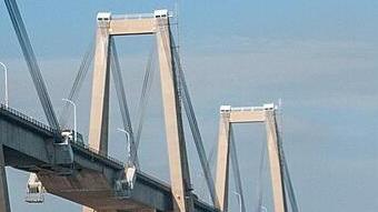
Mike Farish | February 23, 2016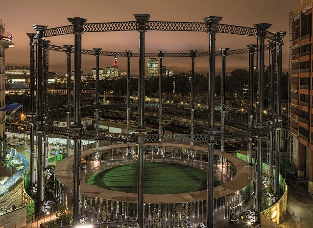 The structure is visible from the nearby Eurostar tracks and helps to recreate a visual signature the area has had for over 150 years. Image credit: John Sturrock.
For more than 100 years, passengers on trains entering or leaving the St. Pancras railway station in London viewed one of the city's more spectacular examples of its industrial heritage – a set Victorian gasholders painted a dark gray and offset by flashes of red and white. The structures were the remnants of a gasworks that were used to help heat and light the city from the mid-19th century until 2000. At one time there were more than 20 of the structures. By the late 20th century, however, the area (which is also cut by a major “highway” from the 18th century, the Grand Union Canal) had become increasingly dilapidated and derelict.
Over the last decade, the area has undergone regeneration. Much of the district now comprises upmarket residential and business space, restaurants and academic facilities.
Greening an Industrial District
In the course of this renewal, the redundant gasworks disappeared. And, for a time, so did all of the distinctive gasholders. But in an innovative project involving a mix of forensic examination, careful dismantling, detailed preservation and targeted re-erection, the outer framework of one of them – the 26-meter-tall and 35-meter-diameter Gasholder No 8 - has been rebuilt near its original location. Project sponsors have added a set of columns that support a thin, perforated roof that runs around the interior to provide a sheltered walkway. Together, the additions form the sculptural surround for a small public garden that adds a touch of greenery to what otherwise is an environment of brick, stone and water.
The resulting structure shows how old and new elements can be combined – the former repurposed and the latter deliberately designed. One source of innovation lies in the structure’s materials. The gasholder is fabricated from 16 hollow cast iron columns held together with two latticed frameworks of wrought iron, one around the mid-point of the columns, the other around their summit. In contrast, the interior canopy and columns are made from mirror-finish stainless steel.
Another innovation lies in methodology. The gasholder structure found its new application as the result of the systematic application of techniques that analyzed a pre-existing physical structure 150 years old. The canopy design, for example, involved intensive work in a virtual world of modern design and analysis software.
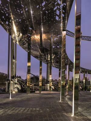 Parametric modelling software was used to help ensure that the column spacing and canopy structure perforations did not cause stresses that might distort reflections from the mirrored surface. Image credit: John Sturrock.A common factor across the project, though, was the participation of consulting engineering firm Arup. For the gasholder elements, the company's engineer in charge was Associate Director Richard Henley. He says that although dismantling and re-erecting old structures is not unusual, he had not heard of the procedure being applied to a 150-year-old structure of this type. But, says Henley, although modern tools and techniques were available to support the project, one fact made the task unusual for a 21st-century engineer – working with 19th century materials.
Careful Dismantling
Cast iron, for instance, has the awkward characteristic of being “strong in compression, but brittle in tension”, which means it “lacks ductility.” In practical terms, the consequence is that when material failure occurs it tends to do so suddenly and without warning. “You really want to be able to see failure happening before it becomes catastrophic,” Henley says. That factor meant the dismantling process would have to be carefully planned in order to minimize stresses to the columns, especially when the supporting horizontal wrought iron elements were removed.
An initial step was to use photogrammetric techniques to create a 3D “'point cloud” model of the existing structure that could be stored in computerized form. Henley says that the technique not only facilitated the use of an appropriate analysis tool to try to predict the likely behavior of the structure as it was dismantled – a program called GSA that Arup wrote and which is commercially available - but also meant that a geometrically accurate record exited of its precise shape. This record could be used as a guide when the structure was re-erected. There were, for instance, some variations in the column spacing that would need to be replicated.
The selected dismantling technique involved building a supporting framework as a protective “cradle” around each column before the wrought attachments to the rest of the structure were released. Each column was then lifted away by crane in two halves, each still in its cradle.
A Dickensian Twist
But, Henley says, this is where a difference between 19th and 21st century working practices became evident. Each half-column length was made up of several shorter sections. Inspection revealed that these had been bolted together from the inside. The lower halves of the columns had a wall thickness of 1.28 inches and a maximum external diameter of 31.5 inches at their base. This tapered to 23.6 inches at their summit. The upper halves were 1.0 inch thick and had an external diameter of 27.6 inches at their base. These also tapered to 23.6 inches at their summit. As such, it was evident that the only feasible way that the internal bolting could have been done would have been if someone small enough to fit inside had tightened the bolts manually. Presumably, Henley says, that person was a child.
Once the dismantling was complete, the structure was taken off-site for cleaning, repair and repainting. Henley says that the metalwork was in surprisingly good condition and that the need to replace material was limited. However, since it was impossible to gain access the internal areas where the column sections had been bolted together, a discrete metal band was positioned around the exterior of each join. The bands are, Henley says, the only consistent visible modern addition to the old structure.
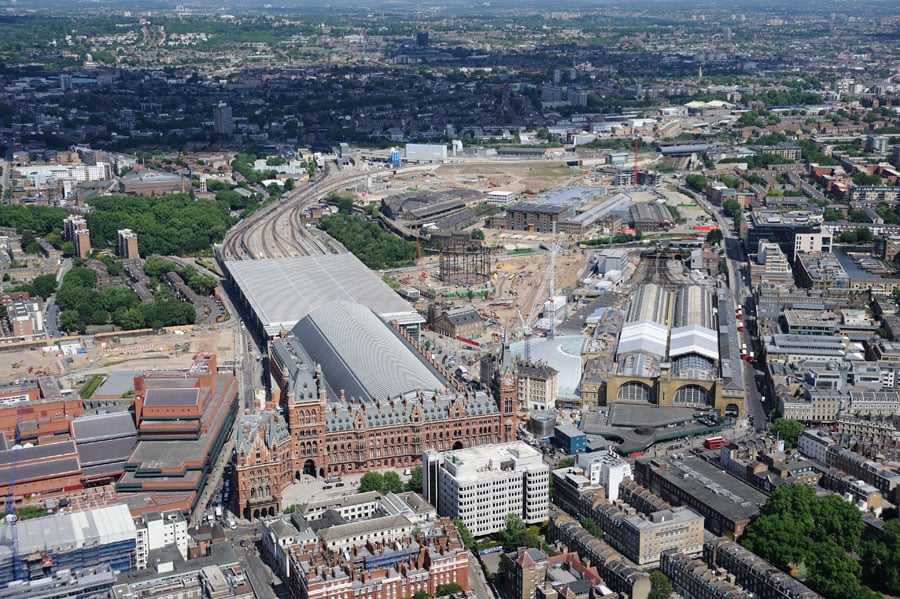 (Click to enlarge.) The project (center) is near the St. Pancras railway station and in a former industrial area that is undergoing renovation. Image source: Arup. The re-erection procedure then became, he says, largely “an inversion” of the dismantling with the half-columns lifted back into place in their cradles. The cradles were removed to allow the wrought iron elements to be reattached. This allowed the structure to stand freely once again over its surrounding neighborhood.
Column and Canopy
In contrast to the relative consistency of the gasholder, the structure’s canopy has been designed to respond to the asymmetrical nature of the site and to taller modern buildings nearby. As a result, the site feels enclosed at one side and expansive at the other. And according to Simon Lindop, also an associate director with Arup, the canopy reflects this in two ways.
The first involves the shape and orientation of the canopy’s two concentric rows of columns. They are rectangular in cross section but are not perpendicular to the walkway. Instead, they meet it an angle of nearly 45 degrees.
The consequence is that when people walk around the pathway with their backs to the canal, they look at the flat faces of the columns. The visual impression is one of an enclosing structure in sympathy with the surrounding buildings. But when the pedestrian walks in the opposite direction toward the more open vista, they face the edges of the columns. This enables them to see through the space more easily and better appreciate the view. The overall effect is further enhanced by the fact that towards the more open side of the site, the physical distance between the columns is progressively increased.
This effect is also echoed in the walkway roof, which is not uniform all the way around. Instead, it is broken by a pattern of rectangular perforations which increase in size and number toward the end of the site closest to the historic canal. Again, someone walking underneath experiences an increasing or decreasing sense of enclosure. But, as Lindop says, creating this illusion required analytical work beforehand in cooperation with the architects Bell Phillips.
Lindop says that Arup used a parametric modelling software package called Grasshopper to help rationalize column spacing in order to provide the most effective support to the roof, particularly in relation to positioning splices between the roof panels. The software also helped determine the positioning of perforations in the canopy roof, which had to take account of the fact that the stresses in the structure were higher at the side farthest from the canal where there were fewer perforations. An underlying objective for both columns and roof, he says, was to minimize deflections so that reflections from the mirrored surface were not distorted. In order to confirm the findings of the analysis, a full size mock-up of a section of the walkway was built.
The combined structure with its associated grassed interior space was opened in November 2015. It now stands about 50 yards from where the Eurostar tracks approach the St. Pancras station and is clearly visible from trains arriving from continental Europe. To the casual observer, the structure might look like a relic but it is something quite different: a mixture of old and new materials to reinvent the area's 19th century visual signature and act as a symbol of the area’s renewal.