Fundamentals of transformer design
Temitayo Oketola | October 06, 2022 Figure 1. The operating principle of transformers hasn’t changed since initially developed, but the designs, efficiency and dimensions have drastically improved. Source: teerapon/Adobe Stock
History is marked by a series of great innovations and inventions that have been vital to the development of modern society. For instance, the commercial generation, transmission and seamless usage of electricity today would not have been possible without the invention of the transformer in 1886.
A transformer is a device that transfers electric energy from one alternating current (AC) circuit to another, increasing (or reducing) the voltage during the process. The operating principle of transformers hasn’t changed since initially developed, but the designs, efficiency and dimensions have drastically improved.
How does a transformer work?
Transformers work on the principle of electromagnetic induction, which explains that electromotive force is produced across an electrical conductor if there is a changing magnetic field.
A transformer contains three major components: the primary winding, secondary winding and magnetic core, as shown in Figure 1. When an alternating current passes through the primary winding, it creates a magnetic flux (or causes a magnetic field to pass through that area). The resulting magnetic field strikes the secondary winding, generating AC voltage through electromagnetic induction.
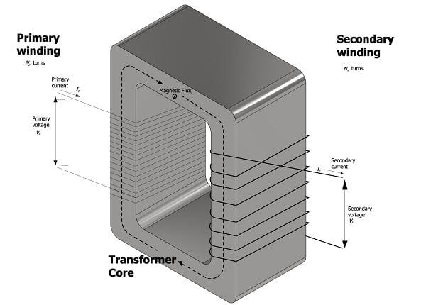 Figure 1: Simple transformer showing primary winding, secondary winding and magnetic core.
A transformer’s primary winding is usually the part connected to an electric power source, while the secondary winding is where power is delivered. The magnetic core simply provides a controlled path for magnetic flux to move between the two windings, which is necessary for voltage induction.
The magnitude of induced voltage depends on the number of turns in the primary and secondary windings of the transformer, as shown in the equation below.

Where:
Vp = voltage in the primary winding
Vs = induced voltage in the secondary winding
Np = number of turns in the primary winding
Ns = number of turns in the secondary winding
For instance, if the number of turns on the primary winding is less than the secondary, then a high voltage will be induced. In contrast, low voltage is induced when the number of turns in the primary winding is greater than the secondary winding. The former scenario is useful when transmitting electricity over long distances, while the latter is used in residential areas for household electric applications.
Basic guidelines for specifying and selecting small single-phase transformers
Determine the required secondary output power
The process of transformer design starts with determining how much power will be needed at the secondary winding of the transformer. And this can be calculated by multiplying the required maximum secondary voltage level by the secondary current, as shown in the equation below:

Where:
I2 = secondary current (A)
V2 = required secondary voltage level (V)
Calculate the primary power rating
Engineers can calculate the primary power rating of the transformer based on the transformer’s expected efficiency. For instance, transformer efficiency usually varies between 80% and 90%, with high power transformers being much more efficient. Therefore, engineers can assume an efficiency rating of 80% for transformers with a required secondary output power rating ranging between 10 W and 50 W. In contrast, the efficiency of transformers having an output power greater than 50 W can be assumed as 90%.
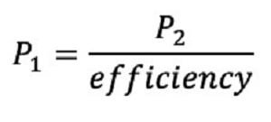
Once this efficiency has been determined, the primary power rating can be determined using:
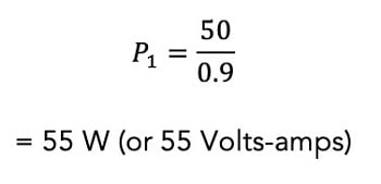
So, assume the required secondary output power was determined to be 50 W, and efficiency was assumed to be 90%. Then the primary power rating is obtained to be 55 W, as shown below:
Determine the required cross-section area of the core
The required cross-sectional area (in cm2) of a small transformer core can be approximately obtained using:

So, consider the previous example of a transformer design having a primary voltage amp of 55 V A. The core area will be obtained as 8.52 cm2. However, it is recommended that engineers design a practical transformer by considering the core sizes available in the market. For instance, engineers are advised to check these standard sizes and choose a core area nearest to (and greater than) the value obtained in their calculation. In this case, an ideal core area would be 9 cm2.
Calculate the number of turns required for the core
The successful operation of a transformer at a particular rating requires that the transformer has a certain number of turns on the primary and secondary sides. Voltage values on each side of the transformer have a direct relationship with the number of turns according to the equation below:

Where:
f = operating frequency of the power system (in Hz)
Bm= magnetic flux density (in Wb/m2)
A = core area (in m2)
T = turns per voltage
For small single-phase step-down transformers, the magnetic flux density typically ranges between 1 and 1.2 Wb/m2, and an operating frequency of 60 Hz is common in the U.S. Therefore, by using a magnetic flux density of 1 Wb/m2 and substituting the value of the area obtained in the previous step, the turns per voltage can be obtained as follows:

Now, using the turns per voltage values, engineers can calculate the required turns on the primary side of the transformer, as shown below:

It is recommended that engineers include about 3% of excess turns in the transformer’s secondary winding to account for the internal drop of secondary winding voltage upon loading. As a result, the required number of secondary turns can be calculated using:

Therefore, consider a simple single-phase transformer with a primary voltage of 220 V, secondary voltage of 30 V and turns per voltage of 4.17. Then the number of primary and secondary turns is approximately 918 and 129, respectively.
Summary
Transformers offer an impressive performance as long as they are correctly specified to meet the application needs. While this article presents helpful information about sizing and specifying small single-phase transformers, the procedure for sizing three-phase systems is more complex. Therefore, engineers and facility managers are advised to reach out to transformer suppliers to discuss their application needs.


