Fundamentals for gears, gearsets and reduction drives
Temitayo Oketola | January 05, 2022
Gears are toothed, compact, positive-engagement mechanical transmission devices that are employed in the transfer of motion and power within different machine components to dictate the torque, speed and rotation direction of the driven machine components.
Gears are considered as one of the oldest pieces of equipment known to mankind, and proof of their application dates back to the 4th century in China. Their importance is even more pronounced in this 21st century as they are applied to almost any device that has a spinning part, from devices as small as wristwatches to machines as large as wind turbines.
How gears work
A gear is a simple mechanical device that transmits power and rotational motion to another gear (or device). A gear typically features teeth that are locked (or meshed) into a corresponding gear, preventing slippage and transmitting power and motion to the corresponding gear. Depending on the gear design, the transfer of motion from the driving gear to the driven gear can be used to increase speed and torque and change the direction of rotation or movement.
(Learn more about gears with Engineering360)
Speed, gear ratio, mechanical advantage and force multiplication
Consider the example of two gears that mesh together. Suppose one of the gears (the bigger one) has more teeth than the smaller-sized gear. It would mean the smaller gear has to rotate several times for the bigger-sized gear to complete one revolution. Mechanical advantage is used to describe the performance of gears, and it can be estimated using the gear ratio of a gear assembly, as shown in the equation below.

So if the gear ratio of the gear assembly is four, it means the force causing the small gear to rotate will be multiplied by four. Therefore, for a gear train with 32 teeth in the larger pulley and eight teeth in the smaller pulley, the gear ratio is four.
Increase in torque
When two gears mesh, the force on the teeth of one gear is exerted on the teeth of the second gear. This force has both a radial and tangential component (see Figure 1), with the tangential force component being the most important in gear calculations since it causes the gears to rotate. The radial component only offers a sideways push on the shaft.
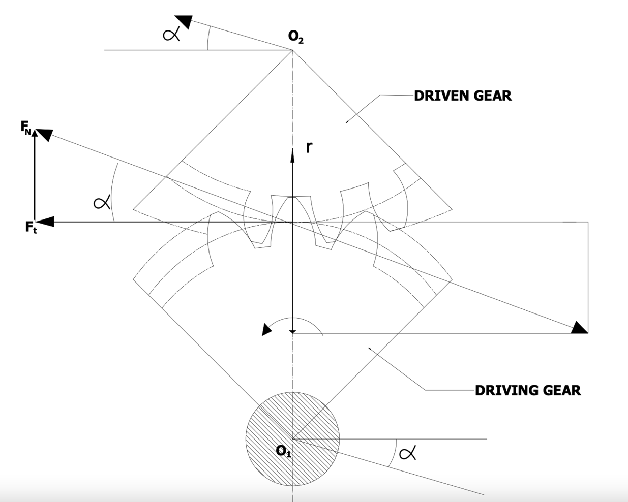 Figure 1. Gear force illustration.
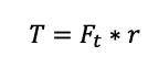
The rotation caused by the tangential force component causes torque on the gear. The larger gear (which was described earlier to be the slower moving gear) has greater torque than the smaller (and faster moving) gear. This torque on the driven gear can be calculated using:
Where:
T = torque
Ft = tangential force component
r = gear radius
Change in direction
When two gears are in a mesh and rotating, the second gear always rotates in the opposite direction. For example, if the driving gear rotates in a clockwise direction, then the driven gear will rotate in an anticlockwise direction. This change in direction attribute of a gear train is very important in several engineering applications, such as in automobiles and ships.
It is also possible to force the power of a machine to turn through an angle by using specially shaped gears. For instance, the gearbox at the mid of a back-wheel drive car (known as the differential) makes use of a cone-shaped bevel gear to rotate the power of the drive shaft through 90° and rotate the back wheels.
(Learn more about differentials on GlobalSpec.)
Gear reduction
Gear reduction is a gear system arrangement that causes the input speed to be lowered, allowing the gear system to achieve a lower output speed at the same (or more) torque. A reduction gear assembly features rotating gears connected to a shaft (or wheel work). This rotating gear assembly transmits the high-speed motion from the shaft, changing the motion and torque.
The desired output torque can be calculated using:
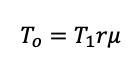
To = output torque
Ti = input torque
r = gear ratio
μ = efficiency of the gear
A typical application of gear reduction assembly is found in automobiles. Automobile engines are designed to operate at a high rotational speed to achieve high efficiencies. However, components like tires of automobiles require a low rotational speed range. Therefore, engineers use reduction gears to reduce the high-speed motion of the engine into the low rotational speed required by the tires and other components.