Lubrication of helical gears
Jody Dascalu | April 16, 2023Helical gears are commonly used in centrifugal compressors, automotive transmissions and turbines. These applications are operating at increasingly higher speeds to help reduce the size and costs of machine equipment. Helical gears are often used to step down the speed of the machine to match motor and generator speeds. As the demand for increased turbine and compressor speed increases, the maximum pitch line velocities of helical gears are increased. Helical gears are well suited for high-speed applications because they generate less friction and subsequently suffer from less wear than other gear designs.
Lubrication is critical to the smooth and reliable operation of systems using helical gears. The primary function of lubrication is to prevent wear on gear teeth surfaces and reduce the amount of heat generated via friction. As pitch line velocities and gear tooth loading increase, so do the requirements for lubrication and cooling.
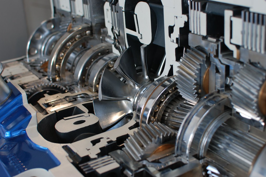 Figure 1: Helical gears in an automotive transmission. Source: Vestman/CC BY 2.0
When gears mesh, the tooth surfaces are in contact with each other as the gear rotates. As tooth surfaces roll and slide, this creates contact and shear stresses. Oil lubricates mating gear teeth and is used to prevent damage from metal-to-metal contact and prevent wear, and scuffing. Oil also cools the gear teeth and prevents excessive temperatures.
Helical gear design parameters
The pitch line velocity, helix angle and axial meshing velocity, pressure angle, surface roughness, face width, and lubricant properties play a role in determining the lubrication and cooling requirements of helical gears.
Historically gears were cylinders that drove each other by friction alone while modern gears take the shape of toothed wheels. Often when designing gears with teeth, they can still be modeled as two cylinders, and many equations relating to gear design rely on this assumption.
The pitch diameter can be calculated with the center distance pitch radius of the pinion and gear, gear tooth ratio, and the number of pinion and gear teeth. The pitch diameter is between the outside diameter of the gear and the root circle of the gear teeth. Pitch line velocity is related to the pitch diameter and is the linear speed of a point rotating on the circle formed from the pitch diameter. Pitch is very integral to gear design as it is used to determine gear shape and gear ratio.
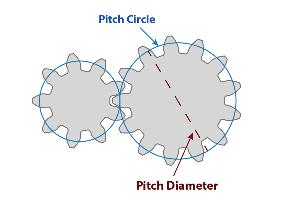 Figure 2: Pitch circle and diameter. Source: Jody Dascalu
Many issues relating to surface distress are functions of sliding velocity. The sliding velocity is the point of contact between meshed gear teeth relative to the pitch diameter. The point of contact of the pinion and gear on the length of the tooth forms the line of action of helical gear teeth.
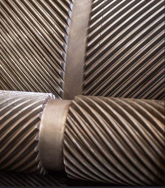 Figure 3: Close-up of herringbone gear, a type of double helical gear. Source: Jez/CC BY-NC-ND 2.0
The helix angle is the angle formed between the axial axis of the gear and the tooth. Helical gears can be single or double helical types. Double helical gears are made with angles between 15° and 30° while single helical gears are manufactured with helix angles between 5° and 20°. In double helical gears, there is no axial gear force, but they are more expensive to manufacture. In single helical gears, larger helix angles correspond with greater axial thrust. On the other hand, lower helix angles correspond with higher axial meshing velocities. In this scenario, trapped oil and air increase in frictional heating as meshing velocity increases. This results in higher gear tooth temperatures, which can result in thermal problems, especially in wide gears.
Face width is the length of the gear teeth. Wider gears mean greater distances for the oil and air to travel, resulting in hotter trapped air and oil.
Gear tooth finish plays a crucial role in managing scuffing and pitting of surfaces. Rough surfaces result in greater friction between mating gear teeth, increasing tooth temperatures. When tooth temperatures are high, the viscosity of the oil also decreases, which increases the possibility of wear and scuffing.
Lubricant properties
Four common lubrication regimes are boundary, mixed, hydrodynamic and elastohydrodynamic (EHD) lubrication. Oils in high-speed gear applications are often classified as inhibited or anti-scuff oils. They are composed of highly refined mineral or synthetic base oils. Additives in the lubrication aid oxidation stability, prevent foam and help to prevent corrosion.
Most oils decrease in viscosity as temperatures rise, but synthetic oils have a lower rate of change of viscosity with temperature. The viscosity of lubrication also changes with pressure. The pressure-viscosity coefficient of lubrications determines the effect of pressure on viscosity.
EHD lubrication refers to the formation of a film of lubrication between mating surfaces in non-conformal machine elements. EHD theory helps determine effective lubrication and smooth operation of machine elements such as helical gears. Machine design is based on the well-known equations presented by this theory.
Surface distress of helical gears
Gear surface distress included scuffing, wear, micropitting and macropitting. The risk of scuffing can be determined through analysis of the lubrication and helical gear properties. Wear occurs when metal is removed or displaced during operation from gear tooth surfaces. Scuffing and pitting are not normally considered as wear. Wear can change the contour of the teeth and results from mechanical, electrical or chemical action. A full EHD oil film where tooth surfaces do not contact each other can prevent wear almost completely.
Micropititng may be difficult to spot with an untrained or unaided eye and is a high rolling contact fatigue incident. It occurs in the Hertzian contact band area. Micropitting can lead to macropitting. While it can occur anywhere on the gear tooth surface it often starts in areas with high sliding velocities at either the top or bottom of the tooth profile. At the pitch line, the sliding velocity is zero, so micropitting typically does not begin to form on the pitch line.
Lubricant properties may affect micropitting and gears that use antiscuffing additives in their lubricants show an increase in micropitting while some other additives may improve micropitting performance.
Macropitting is a surface fatigue phenomenon like micropitting. These pits can be seen by the unaided eye. Macropitting tends to occur when the surface roughness is high and if metal-to-metal contact occurs between gear teeth.
Lubrication choice
The chosen method of lubrication often depends on tangential and rotating speeds. Typically, at low speeds, grease lubrication is a sound choice while at higher speeds splash lubrication and forced oil circulation lubrication work better. In some cases, grease lubricants may be used even at high helical gear speeds.
Lubrication plays a key part in the reliability of a mechanical system. Lubrication and cooling problems are often rare but when they do occur, they can be difficult to solve. As helical gears increase in operating speeds, special attention should be placed on gear design and lubrication properties.
About the author
Jody Dascalu is a freelance writer in the technology and engineering niche. After earning a Bachelor of Engineering, she worked in the manufacturing industry as an analyst. As an avid reader, she enjoys researching upcoming technologies and is an expert on a variety of topics.