Answers to 3 FAQs about spreader beams
Temitayo Oketola | December 27, 2021Spreader beams are simple devices for lifting operations in a broad range of industries. A spreader beam typically consists of a long bar coupled to the end of a crane, allowing the crane to lift loads from multiple locations.
But as simple as a spreader beam’s function might appear to be, there are several things that riggers and engineers must understand when specifying spreader beams for a particular application.
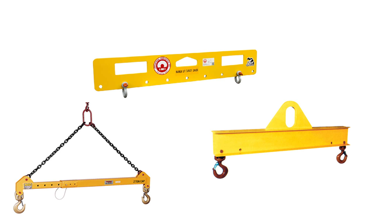 Figure 1. Spreader beams help support uneven or oddly shaped loads for hoisting. Source: Industrial Magnetics Inc.
Spreader beams vs lifting beams: What's the difference?
This question creates confusion among riggers, primarily because spreader beams and lifting beams have similar designs. The answer lies in the way their lugs are oriented, and the type of load (or stress) applied to the beams from the load.
A spreader beam typically features two lugs on top of the beam (one at each end) that attach to the crane’s hook and two additional lugs on the underside that attach to the load. This orientation causes the spreader beams to convert loads into compressive forces (or compressive stress) on the beam.
A lifting beam also features two lugs on the underside that attach to the load. However, unlike the spreader beam, the lifting beam usually has a single attachment point (at the topside) that attaches to the crane’s hook. This orientation causes them to convert lifting loads into bending forces (or bending stress) on the beam.
Spreader beams distribute weight effectively, making them ideal for handling large and awkward load lifts. In contrast, lifting beams are ideal for lifting operations with space limitations since they require little headroom (the distance between the crane hook and the lugs).
How do I calculate the force on a sling connected to a spreader beam?
Consider the simple illustration of a spreader beam attached to a load such that the center of gravity (COG) of the load is in line with the crane hook and the COG of the spreader beam, as shown in Figure 2.
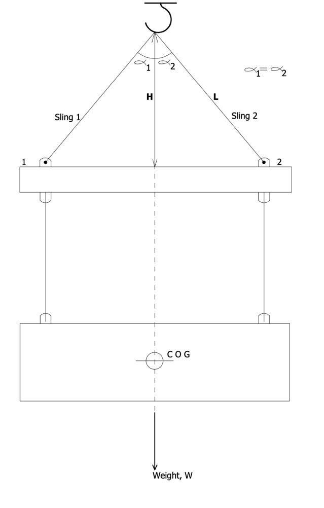 Figure 2. Load on a sling of a spreader beam.
This orientation allows the load (or weight of the object) to be evenly distributed at the two lifting points of the spreader bar. Hence, the force (or tension) on both slings are equal and can be calculated using:

Where:
L = length of sling
H = perpendicular distance from the top of the hook to the spreader beam
W = weight of the object
However, keep in mind that this orientation is not always the case in practical rigging applications; there are several factors that engineers must consider to represent and calculate the tension on both slings accurately. For instance, consider a scenario where the orientation of the spreader beam and load is changed, as shown in Figure 3.
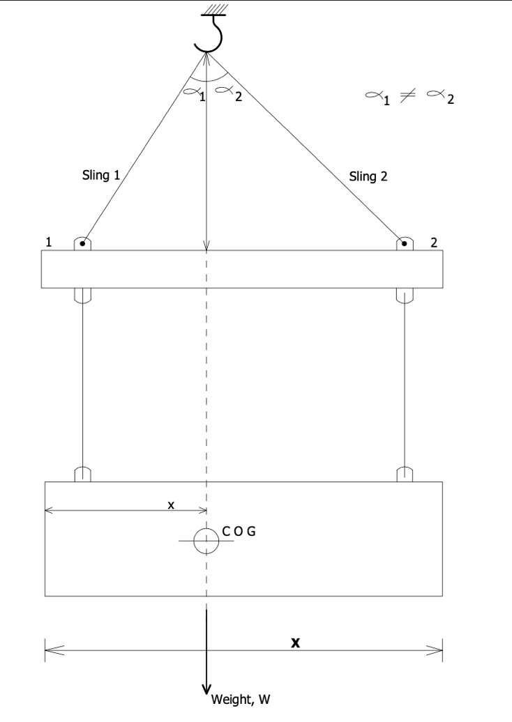 Figure 3. Load on the sling of a spreader beam.
Since the COG is not located at the midpoint of the cargo, the weight experienced at each lifting point differs and can be calculated using this equation.
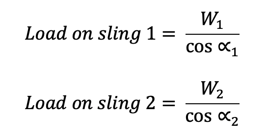 spreader_eq2
Where:
W1 = load at lifting point 1
W2 = load at lifting point 2
As a rule, the sling closer to the center of gravity will take more load than the sling farther away from the COG.
What standards are important for spreader beam?
Two standards that engineers must consider when specifying spreader beams include:
Spreader design
(Learn more about lifting and rigging attachments)
There are still several additional factors and standards that engineers must consider when specifying lifting and spreader beams. For example, engineers still need to determine the compressive and bending stresses on the spreader beam and then compare it to the allowable stresses of the beam.
Engineers are advised to reach out to spreader beam manufacturers to discuss their application requirements to fully attain key principles of spreader design and selection.