Typical operation of potentiometers
Ahmed Faizan Ahmed | July 27, 2021The primary purpose of a potentiometer is the calibration of the voltage of cells. However, the device can be adapted to the calibration of voltmeters, ammeters, resistors, wattmeters and pyrometers. Strictly speaking, it does not measure anything; instead, it compares known values with unknown values, which can be referred to as linear measurement.
A sensitive voltmeter such as a good moving-coil instrument can measure the voltage of a cell. However, no matter how small the current taken by the meter, there is always a voltage drop within the cell due to its internal resistance. Thus, the meter will always register a voltage slightly less than the cell's true potential.
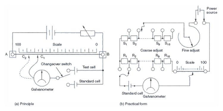
For greater accuracy, a method must be used where no current is taken from the cell when the voltage is measured. This method is known as the potentiometer method and employs the bridge circuit described earlier. When the bridge is balanced, no current is being taken from the cell under test. The basic circuit is shown in Figure 1(a).
 A diagram of potentiometer circuits. Source: Ahmed Faizan Ahmed
A length of resistance wire is laid out against a scale, and a sliding contact is provided so that it can contact the wire anywhere along its length. This resistance wire is shown between points A and B in Figure 1(a). A variable resistor is connected in series with the resistance wire and a DC supply source. The resistor controls the current flowing through the wire and limits it to a value that will enable the wire to remain relatively cool and hence its resistance constant.
If point B is taken as a reference point, the voltage gradient along the wire will vary from zero (at point B) to the voltage of the supply source.
A cell of known voltage is connected in series with a galvanometer between the sliding contact and point B. This cell is usually one called a "Weston standard cell" (see Figure 2). Its no-load voltage is 1.0183 V at 20° C. It is a reliable cell with a constant voltage and is relatively temperature tolerant.
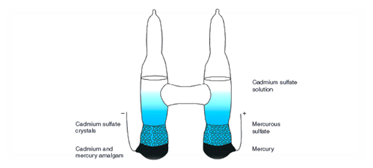 A diagram of a Weston standard cell. Source: Ahmed Faizan Ahmed
A point C1 can be found on the length of the resistance wire where the galvanometer will register zero voltage. This is noted against the attached scale as a distance. Effectively, it is another way of stating that the length of a resistance wire corresponding to BC1 bears a direct relationship between the voltage gradient along the wire and the voltage of the Weston cell.
The cell to be tested then replaces the Weston cell. (In Figure 1(a), a changeover switch has been provided.) A balance is again found by adjusting the sliding contact (at point C2). By calculation, these lengths can now be transformed into the required voltages by a simple ratio.
Example
A potentiometer was used to test the voltage of a cell. The distance for balance with a Weston cell was found to be 77.8 cm, and the length for the test cell was 58.3 cm. To find the voltage of the test cell:
Solution
![]() illustartion1
illustartion1
The above description illustrates the principle of the potentiometer. Modifications have been introduced to simplify its use and to improve its accuracy. First, the length of the slide wire section was increased to something like 7 m. This made the instrument rather cumbersome to use and calibration tedious. Next, the wire was split into sections, requiring only the last section to be calibrated in terms of length.
The modern version uses standard resistors, which take up far less room. The sliding scale is retained. This can be seen in Figure 1(b). Note also from the diagram that instead of a variable resistor for the power source, two adjustable resistors are used. One is for coarse adjustment, the other for fine adjustment. Each controls the amount of current taken from the power source.


