Control valve sizing guide
Ken Thayer | June 25, 2019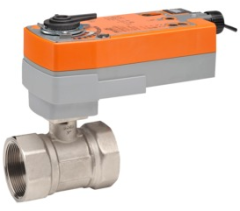 Characterized control valve. Source: Belimo
Control valves are important components for successful control of fluid flow in process plants and systems. Control valves include many different valve types, including rotary motion valves such as ball, butterfly and plug valves, and linear motion valves such as gate, globe and diaphragm. They can also be classified by their function as either flow regulation or on-off. To guarantee optimum system performance, control valves must be sized properly.
A guideline for proper sizing is to select a valve that it is between 20% to 80% open when operating at the maximum flow rate and no lower than 20% when operating at the minimum required flow rate. This allows the valve to be used over most of its operating range while maintaining a reasonable but not excessive safety factor.
Valve sizing typically starts with the calculation of the flow coefficient (Cv). Flow coefficient is defined as the number of U.S. gallons per minute of water at 60° F that will flow through a valve at a specified opening with a pressure drop of 1 psi across the valve. The flow coefficient is used to calculate the valve size that passes the desired flow rate while maintaining stable control of the process fluid.
Liquids
For liquids, the flow coefficient is calculated as follows:

Where:
- Q = flow rate (GPM)
- S = specific gravity of fluid relative to water at 60° F (1° F for water)
- ΔP = pressure drop at maximum flow = P1 - P2
- P1 = upstream pressure (psi)
- P2 = downstream pressure (psi)
Example:
Find the flow coefficient given the following conditions: Q = 20 GPM, media = water (S=1), pressure drop = 20 psi

 Specific gravity for various liquids; Source: IEEE GlobalSpec
Air and gas
The flow coefficient varies depending on the media type and is different for steam and gases.
For air and gases, the flow coefficient is calculated by two different formulas, one for critical flow and one for subcritical flow.
Gas and air are compressible fluids and must be checked for choke-flow conditions prior to calculating the flow coefficient. Choked-flow situations occur when the downstream pressure (P2) is greater than one half the upstream pressure (P1). When this occurs, the flow reaches the speed of sound and changing the downstream pressure does not increase the flow.
For critical flow in choked-flow situations, when the downstream pressure is greater than one half the downstream pressure (P2 > 1/2 • P1) the following formula applies:
Use this formula for subcritical flow when the downstream pressure is less than or equal to half the upstream pressure (P2 ≤ 1/2 • P1):
Where:
- Qg = air or gas flow, standard cubic feet per hour (SCFH) at 14.7 psig and 60° F
- G = specific gravity of gas relative to air at 14.7 psig and 60° F
- T = air or gas temperature (° F)
- ΔP = pressure drop at maximum flow = P1 - P2
- P1 = upstream pressure (psi)
- P2 = downstream pressure (psi)
 Specific gravity for various gases; Source: IEEE GlobalSpec
Steam
Steam is calculated with one of the following two formulas.
For critical flow, when the downstream pressure is greater than one half the upstream pressure (P2 > 1/2 • P1):

For subcritical flow, when the downstream pressure is less than or equal to half the upstream pressure (P2 ≤ 1/2 • P1):

Where:
- W = Steam flow, pounds per hour (lb/hr)
- ΔP = pressure drop at maximum flow = P1 - P2
- P1 = upstream pressure (psi)
- P2 = downstream pressure (psi)
Standards
The Instrument Society of America (ISA) produces several standards regarding control valves.
- ISA 75.01.01 — Industrial-Process Control Valves — Part 2-1: Flow capacity — Sizing equations for fluid flow under installed conditions
- ISA 75.02.01 — Control Valve Capacity Test Procedures
- ISA 75.05.01 — Control Valve Terminology
- ISA 75.11.01 — Inherent Flow Characteristic and Rangeability of Control Valves
Discover more
Subscribe to Engineering360 Newsletters for industrial and engineering news and information: