FCAW-S difficulties and how to overcome them
Shawn Martin | March 20, 2024Self-shielding flux core arc welding (FCAW-S) offers several advantages over other welding techniques. It combines the mobility and omnidirectional welding benefits of a fluxed electrode with the productivity of a wire-fed electrode. It offers protection in dirty/windy environments and is the preferred welding technique for a number of field operations. In spite of its advantages, however, FCAW-S also introduces unique challenges.
FCAW-S basics
In FCAW-S, a fluxed core wire functions as the consumable electrode. It is fed through a liner to a torch and through a contact tip by a wire feed unit. The metal sheath of the electrode is a filler metal and the fluxed core provides both a shielding gas and protective slag. The gas envelopes the arc while the slag shields the molten weld pool as it slowly cools.
The self-shielding fluxed core wire provides the same benefits of a stick electrode used in shielded metal arc welding (SMAW). This type of shielding protects the weld pool in field operations where environmental factors render gas-shielded processes ineffective. It also provides for increased deposition rates, reducing the time it takes to join large profiles and thick plates. FCAW-S is the preferred technique for a number of field operations including structural steel, shipbuilding, pipelines, general repairs and other field applications involving a variety of profiles.
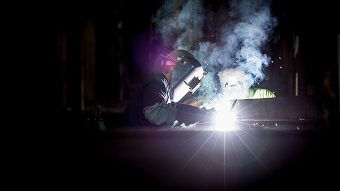 Figure 1: FCAW-S features a number of benefits but also introduces unique challenges.
To realize the benefits of FCAW-S, it is important to dial in the voltage. A constant voltage (CV) power source is preferred, as voltage spikes result in an increased arc length and a greater potential for atmospheric exposure. At the other end of the power spectrum, voltage drops result in poor penetration and slag inclusions. Alongside use of a CV power source, considering a number of other factors can prevent wire feed problems and eliminate or reduce the occurrence of welding defects.
Overcoming wire feed problems
Wire feed issues not only limit productivity, but also lead to weld discontinuities that weaken the joint. The two most common wire feed problems associated with FCAW-S are burnback and birdnesting.
Burnback
Burnback occurs when the melting wire actually forms a weld in the contact tip. In most cases the contact tip is completely lost and requires replacement. Commonly, burnback is due to an inadequate wire feed rate. Incorrect contact tip sizing or holding the torch too close to the workpiece can also cause burnback. To prevent the phenomenon, welders should ensure that the wire feed rate is matched to the specification of the fluxed-core wire, that the correct contact tip is used and that the contact tip is kept at a distance of no more than 1-1/4 in from the workpiece.
Birdnesting
Birdnesting is the tendency for the wire to become tangled in the wire feed unit. Self-shielding FCAW wire is highly susceptible to birdnesting as the fluxed core is easily compressed by the drive roller. Use of an incorrect liner, incorrect drive rollers, failure to properly trim the liner or poor tension in the drive roll can all result in birdnesting. When welding with FCAW, knurled V-groove drive rollers are ideal for the wire feed unit. Welders should select a liner that is sized to the diameter of the welding wire, adjust drive roller tension, trim the liner according to manufacturer specifications and inspect both the liner and torch for blockages.
Preventing welding defects
Welding defects greatly reduce joint strength, and while no joint is perfect the following recommendations can help reduce the chance for a number of welding defects associated with FCAW-S.
Porosity and wormholes
Porosity and wormholes are discontinuities that develop in the weld pool when gas becomes trapped. Wormholes are nothing more than elongated gas inclusions. The gas is introduced either from the fluxed-core itself or from the surrounding environment when the arc length exceeds the shielded area surrounding the weld pool. To reduce the likelihood for any amount of porosity, it is best practice to clean the workpiece and remove any oxides, coatings, oil or other foreign material. Additional best practices include supplying voltage based on amperage and wire feed settings, and keeping the wire electrode length within 1-1/4 in of the contact tip.
Slag inclusions
The protective slag that shields the weld pool can also give rise to inclusions, jeopardizing the integrity of a welded joint. Slag solidifies quickly, allowing the molten weld pool to slowly cool and improve its metallurgical properties. Well-maintained travel speed and angle can prevent slag inclusions.
A drag angle between 15° and 45° is recommended for flat, horizontal and overhead weld positions, while an angle between 5° and 15° is recommended for vertical welds. Slag inclusion may also occur if there is insufficient voltage and heat input. Lastly, when multiple passes are required the joint should be thoroughly cleaned between each pass with a bead placement that provides sufficient space for successive passes.
Undercutting
Undercutting occurs when the base metal adjacent to the toe of the weld melts and a groove is developed. It creates a void that weakens the joint and may lead to cracking. To prevent undercutting gun angle, voltage and amperage should all be in line with the given weld position and filler metal. Welders should also take care to completely fill in melted-out areas of the base metal near the joint.
Conclusion
Weld technique and process parameters are the single largest factors that affect weld quality when using FCAW-S. While most do not consider FCAW-S a difficult welding technique, the process is often tricky when compared to traditional shielded metal arc welding operations. In FCAW-S operations wire feed adjustments, liner selection, use of a constant voltage power source and machine set-up are paramount in order to achieve increased throughput and a structurally sound weld.


