What to Look For in a Thermal Design Solution
December 20, 2016Sponsored content
 Computational fluid dynamics (CFD) is the analysis of systems involving fluid flow, heat transfer and associated phenomena through the use of computer-based simulation. These solutions enable engineers to model thermal responses including all the modes of heat transfer, namely conduction, convection and radiation. The results can be used to judge design viability—keeping component temperatures within specification is one of the criteria used to determine the acceptability of a design—and enable a design team to commit development resources with confidence in an environment where even short delays can lead to a missed market opportunity.
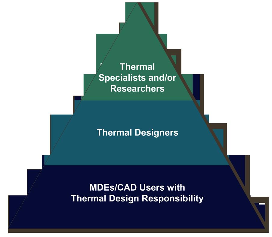
CFD-based thermal simulation and design tools have traditionally been aimed at engineers with specialist knowledge. However, CFD-based thermal simulation users now also include mechanical design engineers, electrical engineers, industrial designers, and even engineers whose primary assignment is in marketing. So the engineers responsible often are not experts in CFD or fluid dynamics and they do not want to spend a lot of time learning detailed CFD concepts or running potentially time-consuming operations. Hence the need for EDA-friendly CFD-based thermal design solutions that are quick, reliable, and integrated into fast-moving, complex design processes. And these usefully-accurate solutions have to be obtained in the hours available, usually on desktop computer hardware.
When selecting a thermal design solution a number of factors should be taken into consideration, including (not listed in any special order):
The ability to integrate with MCAD and ECAD data
Design complexity is driving MCAD and EDA design flows closer together. Mechanical engineers collaborate with electronic designers using EDA software and with other mechanical designers using MCAD software. Thermal simulation and design software contributes to all stages of the design. So tight integration between MCAD and EDA is needed to eliminate design conflicts and accurately capture effects such as Joule heating (also known as resistive or Ohmic heating), which is the power lost to heat as electrical current flows down a conductor such as in traces, PCB/BGA substrate power, and ground planes.
The accuracy of the thermal model
Whether the electronics are on a server or a mobile device, the best thermal design or temperature management scheme requires accurate thermal models. You expect that your thermal model will be accurate, true, and precise and deliver reproducible results within a given range. The model must be calibrated against test data —and not just the usual static point temperature measurement data, but measurement data that captures the transient response of the device. Calibration determines whether your model is correctly delivering measured values or needs an adjustment. The value of a calibrated model is limited by the quality of the measurement results on which it is based.
But calibrating or validating analytical models isn’t easy. There are uncertainties associated with the data that is input, such as material properties, the thermal connection between parts of different materials, test setup, and the measurement data. The calibration process involves exercising an analytical model in the areas where there are uncertainties. To fully understand the implications of each uncertainty during the calibration process takes significant engineering time, and much interpretation. Often the finite amount of engineering time and limited measurement data of the calibration process produces a model calibration considered just “good enough,” resulting in a number of ongoing issues. Best-guess models are quite common. But they can be significantly different than a fully-calibrated model. If you have the peak temperature incorrect, for example, the three-dimensional temperature and temperature gradient distributions will be different as well.
Risks associated with using uncalibrated models include reliability, longer design cycles, and under- and over-design. An uncalibrated model will either over-predict temperature, which will lead to over-design, or under-predict temperature which will directly affect reliability To ensure model accuracy, the simulation and experiment structure function must match across all package elements. The structure function is the thermal capacitance versus thermal resistance of the heat transfer path. The structure functions are obtained by direct mathematical transformations from the heating or cooling curves. These curves may be obtained either from measurements or from the simulations of the detailed structural model of the heat flow path. With a calibrated model we ensure that each object in the package is modeled correctly, that the three-dimensional temperature field is accurate, and that the model includes all time constants, and therefore it will respond accurately, regardless of what the transient power-driving profile will be.
 Quick modeling results
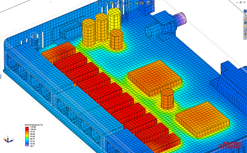
Heat transfer and fluid flow design analysis software has matured, growing both in ease of use and in modeling prowess. Before computer modeling was available, the only way to find out whether a heat removal method worked was to build a physical prototype and measure it. Now, computer-aided thermal modeling avoids expensive physical prototyping iterations and you'll probably only have to build once.
The availability of an XML schema
XML stands for Extensible Markup Language. It is a software- and hardware-independent tool for storing and transporting data that was designed to be both human- and machine-readable (including objects, attributes, mesh and solver control settings, etc.) An XML schema allows geometry and attribute data to be written to a file by user-created scripts for subsequent import into the thermal design solution. It facilitates the creation of objects which are geometrically repetitive in their construction (e.g., folded fin heat sinks), which would normally be time consuming or tedious to build. What’s more, if there is a class of geometry that you wish to create variations of often, you can write your own XML generating macro.
Optimization
To get closer to designing the best and most profitable products for their functions, engineers are turning to optimization. Design optimization can increase the value of a product by improving its performance within its operating environment, and by reducing production cost by trimming the amount of material used to make it. Optimization also increases an engineer’s knowledge of his or her product’s behavior. The tools used are very important to optimization because the method of creating models and dimensioning schemes affects the designer’s ability to explore design alternatives. Many of today’s design processes are driven by optimization tools that are able to control a finite element analysis (FEA) model, a thermal model, etc. and these tools offer drag and drop functionality.
Efficient use of supply chain resources
Does the numerical modelling package enable thermal simulation of real-world electronics, including a wide range of parts from components to ICs to PCBs from a large list of suppliers? Does it streamline model creation to minimize solve times and maximize solution accuracy?
Also of great importance to the supply chain is the ability to share results with management and customers. At the end of the calibration process, you'll have a model that will provide accurate answers in any steady state or transient application. It's vital in many cases to be able to demonstrate to your customers that this accuracy exists. By providing the simulated structure function on the same chart as the experimental structure function, you can supply these models downstream to customers so that they can make informed design decisions with confidence. In this way the model has value to suppliers not only for meeting their internal design needs, but also by allowing vendors to provide models to their customers that are known to be accurate to include in their design.
Checking off the boxes

In summary, then, what you want is an automated method of generating a calibrated model with a quantifiable degree of accuracy. The calibration process should provide a repeatable measurement that is able to accurately capture small temperature differences between the source and environment. That measured thermal response can then be converted into a structure function curve; with, say, the thermal resistance on the x-axis, and thermal capacitance on the y-axis path that the heat takes from the junction.
This yields very useful information, as it has been shown that you can directly correlate sections of a structure-function curve to physical objects that the heat encounters. It also allows engineers to understand the physics of why and how they observe the thermal response the way they do. The structure functions can be looked at from the simulated test environment, and then directly compared to the structure functions recorded in the lab. Directly comparing structure functions between simulation and experiment ensures that the result correlates well to the physical object.
As a consequence you can build a detailed model of a package that's being tested to provide insight into the complete heat flow path, from die through IC package, PCB, chassis, and to ambient.
You also want to be able to define how many scenarios should be created. Given the uncertainty with material properties, material connectivity, and physical features there probably are a number of design scenarios that need to be considered during the calibration process. So if you choose 30 you should be able to get 30 unique combinations of design parameters, effectively filling the design space that has to be defined.
Once you’ve found the best answer you then should be able to easily find the scenario that is calibration optimum. From that you can then quickly determine what values of your design parameters resulted in the best case, and save that as a model for distribution to the system integrator, who will be confident of the accuracy of the provided model.


