Model continuity: From offline simulation to real-time testing
Jost Allmeling, Plexim GmbH | February 05, 2020Simulation models help developers in many ways during the entire development process of a new power electronics application. At each development stage, components are verified with appropriate test tools and procedures before being integrated into a larger system. While each stage may use models with different levels of detail, it is important to ensure that the models used produce comparable results. Although achieving this by working with a single model seems impossible, many benefits can be realized today with the right development process and an appropriate toolchain.
Conceptual development
Simulation software used in the conceptual development phase must provide generic models for all types of electrical components encountered in power electronic applications. As power semiconductors are normally operated in switch mode they should be modeled as ideal switches to reduce the complexity of the simulation model. The user must be able to freely connect arbitrary components and to create his or her own customized components by means of subsystems.
During the conceptual phase, the system model can grow in complexity and size. In order to obtain fast transient simulations without significant integration errors, the use of a variable time-step solver is strongly recommended. A variable step solver automatically steers the time step in such a way that the maximum integration error is not exceeded and switching instants and other discontinuous events are hit exactly.
Component development
Based on the current and voltage requirements determined by the circuit design, suitable components with specific part numbers are selected and the mechanical layout is created. In this phase of development, simulations help to predict the thermal losses and the resulting temperatures generated by the electrical circuit. They also model the heat transfer.
Switching and conduction losses can be simulated efficiently using a set of loss tables for each semiconductor. The advantage of using loss tables over simulating voltage and current transients during switching is that ideal switching and thus high simulation speed is maintained. The computation of the thermal domain adds some extra effort to the electrical simulation based on ideal components.
Mechanical design development
The mechanical design, which is carried out in the next phase, includes the placement of the components, the electrical layout, the design of the cooling system and the integration into a housing.
Due to the enormous effort involved in using spatial information and obtaining detailed semiconductor models to determine the influence of parasitic inductances and EMI effects, as well as the limited gain of new insights, the model tool chain is typically broken at this point and such low-level simulation is often omitted.
Controller development
In the classical approach, experienced software developers will implement the control code for a specific target MCU according to the specifications of the control engineers. Implementing embedded control code, though, requires continuous testing. This can be simplified by compiling excerpts of the control code into a DLL destined for the host computer instead of the target MCU. Most system simulation software can include DLLs so that the control code can be verified against a model of the controlled system.
A more modern approach to implementing controls on an MCU is to automatically generate target-specific C code from the functional block diagram. In addition to its offline implementation, each block must provide a method for outputting real-time capable C code. The block diagram typically contains generic signal processing blocks as well as target I/O blocks to configure the on-chip peripherals. Auto-coding speeds up the development enormously. With respect to model continuity, auto-coding has the advantage that the generated code always adheres to the block diagram definition.
Controller testing
 Figure 1. Figure 1: Plexim’s new RT Box portfolio. Source: PleximHandwritten or automatically generated code can be verified against the block diagram definition in an offline simulation by replacing the block diagram with the compiled code. This type of verification is called software-in-the loop (SIL) testing and allows for short turnaround times since no MCU needs to be flashed. However, the proper configuration of MCU peripherals cannot be verified with SIL, nor can timing issues, processor utilization or resource corruption be detected on the target MCU.
Testing not only the control code, but the entire control hardware, including the MCU peripherals, normally requires the real power stage to be connected to the controller. However, this is often impractical.
To test the control hardware independently of the power stage, the controller can be connected to a real-time simulator that mimics the behavior of the power stage. This approach is referred to as hardware-in-the-loop (HIL) simulation, as the actual control hardware is part of a closed loop-simulation. Replacing the power stage with a real-time simulation has the advantage that the behavior of the controller can be extensively tested under a large number of normal and faulty conditions.
The challenge with HIL simulations of power electronics are the small time constants prevailing in electrical circuits. Only a short additional latency is acceptable, which is inevitably introduced by the real-time simulator. The computational latency between capturing the PWM signals and providing simulated sensor signals to the controller should be kept to a minimum, since the controller should still behave as if it were connected to the real power stage. This requires real-time hardware in addition to converter models optimized for fast and accurate execution in fixed time-step simulations.
Conclusions
Using the same model for all simulations throughout the development process from design to verification is an ideal goal that is difficult to achieve in practice. Aspects such as system or device behavior may require various simulation tools and models with very different levels of detail. Obtaining a single “digital twin” that resembles the entire system and using this twin as the single source of truth is therefore illusory.
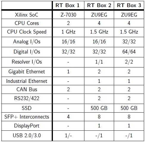 Figure 2. Comparison of RT Box models. Source: PleximNevertheless, it is perfectly realistic to establish a development process in which all system parameters are stored in a central location and referenced by all models. Certain parameters will be used only by some models for simulating selected aspects. Using an integrated toolchain like PLECS helps to verify models for different purposes against each other and thus enables model continuity.
Featuring its end-to-end interoperability with the PLECS simulation software, Plexim’s PLECS RT Box was developed to address the shortcomings of conventional real-time platforms for HIL testing and provide comprehensive solutions supporting the continuity of simulation models of power electronic systems. At the push of a button, a PLECS model is converted into real-time C code, compiled, uploaded and started on the RT Box. With the external mode real-time simulation data from the RT Box can be displayed in PLECS scopes and compared with results from offline simulations.
For more information on how the PLECS RT Box enables model continuity, visit the Plexim website.


