Basic types of antennas
Seth Price | January 11, 2023Antenna design requires understanding the relationship between the transmitting and receiving frequency, directionality, polarization, impedance and the geometries of different antennas. This article will evaluate several different antenna designs and describe their strengths, differences and how to calculate the dimensions for each of these geometries.
The truth is that every antenna is a compromise of some sort. A compact antenna trades gain and bandwidth for a portable size, directional antennas trade simplicity (often requiring a rotor) for directional gain. Part of the fun with antenna design is constantly tweaking antennas to boost their performance for a specific application.
Vertical antenna
Vertical antennas are perhaps the most familiar antenna, and probably what comes to mind when one thinks of antennas. Vertical antennas are typically fed from the bottom and generate a vertically polarized wave that is omnidirectional.
As it turns out, the vertical part of the antenna that one sees is only half of the story. In order for a vertical antenna to work properly, it must have a ground. This is because the vertical antenna is really half of a dipole antenna, where the other half is in the ground. The most common way to build a ground for a vertical antenna is by placing ground radials, generally wires, that extend from the base of the antenna outwards in all directions. A good radial system will have at least 16 radials, evenly spaced, where each radial is ¼ wavelength long.
In order to design a vertical antenna, the radiating element should be ¼ wavelength long. It can be constructed from aluminum tubing or, in some cases, out of a wire suspended from a higher point, though this is less common.
Dipole antenna
Think of a dipole antenna as a horizontally oriented vertical antenna. Instead of an antenna sticking up from the surface with a network of ground radials, however, there are two, equally sized radiating elements, horizontally oriented in opposite directions.
Dipole antennas are sometimes called “half-wave” dipoles, as each radiating element is ¼ wavelength long, making the total length of the dipole a half a wavelength long. They can be made from tubing or from wire, though longer antennas are often made from wire, and supported at the center and the two ends. In the center, there is an insulator that separates the two parts of the transmission line (center conductor and shield for coaxial cable), and an insulator at each end of the dipole.
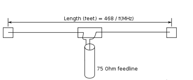 Schematic of a dipole antenna. Source: Tiger66/CC BY-SA 3.0
When choosing a location to suspend a dipole antenna, virtually any support can be used. However, even a 100 W output can generate high voltage at the end of the wire, so these ends should be high enough that the passer-by cannot touch it. Furthermore, there should be some distance between the end insulator and the support structure. Also, for optimal performance, the dipole should be ¼ wavelength off the ground.
A dipole antenna will radiate in a broadside pattern, leaving nulls at each end. Therefore, a west-to-east oriented dipole will have some coverage gap due west and due east. The nulls can be deep, such that a signal in the direction of the null can disappear entirely. Because of this, rotatable dipoles can be used for direction-finding, just rotate the antenna until the signal disappears.
Because of their ease of construction, many amateur radio operators have experimented with different dipole configurations. In a pinch, dipoles can be fed off-center, meaning one element is longer than another that changes the radiation pattern, based on antenna height and transmitting frequency. The ends can be placed at different heights, leading to nicknames such as “sloper” where one side is higher than other, or “inverted-v” where the center is higher than either end.
Dipoles can also be folded back on themselves. This changes the input impedance and the radiation pattern, but makes the antenna more compact.
Yagi (beam) antenna
The Yagi, or beam antenna, was a really common design for homeowners who wanted to receive over-the-air television broadcasts. By their nature, they are directional, so it made sense to point them in the direction of the television station. For folks that lived between multiple metropolitan areas, a rotor could be used to point the antenna towards one station or another.
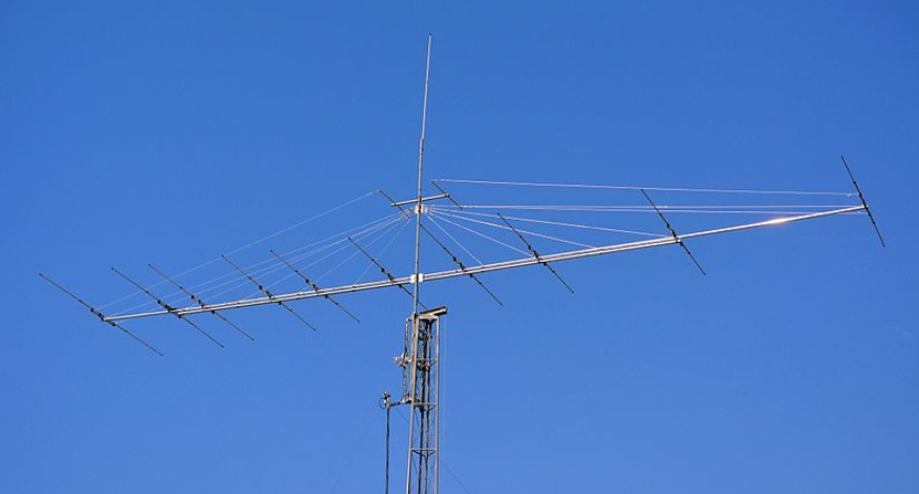 A 10-element Yagi antenna used for amateur radio. Above the beam are some support wires to stabilize the antenna. Source: F5oux/CC BY-SA 4.0
One of the important parameters with Yagi antennas is the “Front to Back Ratio”, which is a measure of the gain in the direction the beam is facing versus directly behind the beam. A high front to back ratio means the antenna is highly directional.
Beam antennas have at least two elements. They have a driven element that is connected to the feedline through an impedance matching network, and they have a reflector at the minimum. Most beam antennas also have a director element, but it is not required. Furthermore, the antenna may have multiple directors; the more directors, the longer the beam, but the higher the front to back ratio and the gain.
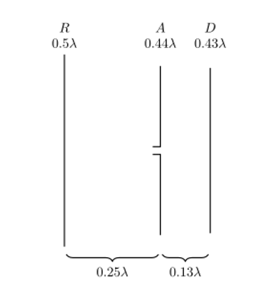 This diagram shows the spacing of the elements on a beam antenna (minus the supporting beam), as imagined by Shintaro Uda and Hidetsugu Yagi. In this figure, the antenna would be “beaming” to the right. The patent was filed by Yagi, though some call these antennas “Yagi-Uda”, as Uda was the original designer. Source: Sankeytml/CC BY-SA 3.0
The general idea with a Yagi is that the signal is fed into the driven element, which is simply a dipole. Behind the driven element is the reflector that reflects some of the signal forward. Then each of the directors resonate at the transmitted frequency. The end result is several signals (one driven, one reflected and then some resonation) combine in-phase to produce the gain and the directionality of the overall signal.
Final thoughts
These are just a few basic categories. There are many other types of antennas out there, and more are being developed by radio experimenters every day. Some are being developed in radio laboratories at major universities, while others are being modeled with Finite Element Methods (FEM) by amateurs using software packages, such as EZNEC.
Some folks will swear by one type of antenna, as it functions for their purposes, even if it may not be as efficient. Because all antennas are a compromise of one form or another, this is the nature of antenna design. However, good engineering principles will lead the designer to thorough testing and a few calculations to ensure that the antenna is working to the best of its abilities