Fundamentals of three-phase motor starters
Ahmed Faizan Ahmed | September 28, 2020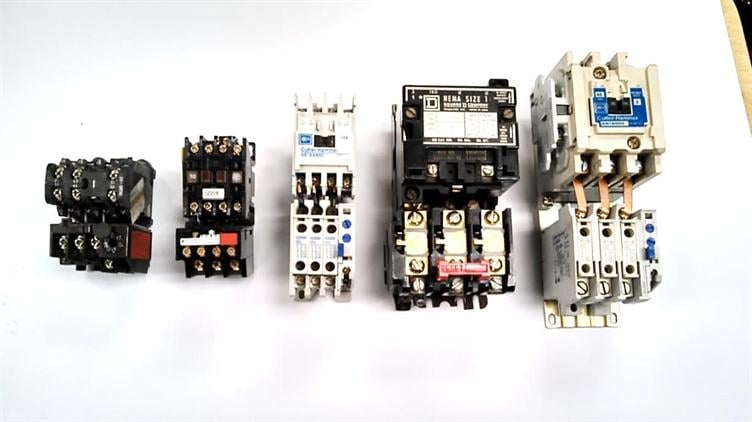 Figure 1. Three-phase (three-pole) electromagnetic across-the-line motor-starters.
Three-pole (three-phase) electromagnetic motor-starters (Figure 1) are commonly used to control integral-horsepower three-phase AC induction motors. This type of three-pole motor-starter is usually described as a three-phase across-the-line or full-voltage motor-starter because full line voltage is applied to the respective motor leads when the motor-starter solenoid coil is energized.
The three-phase electromagnetic motor-starter consists of a power contactor and an overload relay, as shown in Figure 2. The mechanical closing of the power contacts is accomplished by an electromagnetic field, which is produced by a coil of wire contained in the solenoid. The solenoid coil can be activated with an electrical signal from a remote location.
The contactor
Within the construction of the three-pole electromagnetic motor starter, the contactor is a power contactor (Figure 2). It uses a solenoid to electromechanically engage (by generating linear motion) all three power-switching contacts simultaneously when the coil is energized. The linear motion of the solenoid coil in the three-pole electromagnetic motor starter replaces the handle of the switch used in the three-pole manual starter.
Auxiliary control contacts
The three-pole electromagnetic motor starter is usually supplied (purchased) with a minimum of one set of NO (normally-open) auxiliary contacts (Figure 2) that are activated with the power contacts. These NO auxiliary contacts can be used as a switch to control indicating lights, other three-pole electromagnetic motor-starters, or the necessary seal-in contacts in a three-wire control circuit.
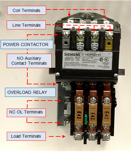 Figure 2. Component layout of a common motor starter. The power contactors of some three-pole electromagnetic motor-starters are fitted (furnished) with both a set of NO and a set of NC auxiliary contacts. Both types of contacts are activated (held-closed and held-open, respectively) when the power contacts are closed.
The NC auxiliary contacts can be used to turn off a light when the motor is running (motor-starter activated). They can also be used to disable another control function, such as the lockout (disabling) of the opposite direction coil on a reversing three-pole electromagnetic motor-starter (the motor cannot run in both directions at the same time).
The NC auxiliary contacts can further be used to lockout the three-pole electromagnetic motor-starter of a second motor when two motors cannot be operated simultaneously. These control contacts are referred to as auxiliary contacts because the primary function of a three-pole electromagnetic motor -starter lies within the switching of its power contacts, which controls the power applied to the motor windings.
Overload relays
As used with the three-pole manual motor starter, the overload relay of the three-pole across-the-line (electromagnetic or full-voltage) motor starter consists of three heating elements wired in series, one each, with the three motor-supply leads. The three supply terminals of the overload relay usually are bolted directly to the load terminals of the three-pole power contactor. The load terminals of the overload relay, marked T1, T2 and T3, are the motor supply terminals. By means of motor-circuit conductors, these overload-relay terminals must be connected to the three-phase AC motor leads T1, T2 and T3 in the motor terminal housing.
The overload elements (heaters) in the three-pole electromagnetic motor-starter’s overload relay, which are sized according to a manufacturer’s heater table and a limited over-percentage of the actual (nameplate) motor full-load current, must be installed in the respective slots on the overload relay (one in series with each of the three motor leads).
The overload relays for lower-rated integral-horsepower three-pole electromagnetic motor-starters usually contain a single set of control contacts, which are held closed by mechanical linkage to all three of the heater elements. If any leg (phase supply) of the motor should draw current in excess of the heater element’s current rating, that respective heater will release the control contacts. These contacts, when wired correctly in the control circuit, will interrupt control power being applied to the motor-starter solenoid.
Higher-rated integral-horsepower three-pole electromagnetic motor-starters may have individual overload relays installed in each motor supply conductor. The NC control contacts of the three individual (separate) overload relays are usually wired in series at the point of a manufacturer. Some schematics may show all three overload contacts. Others will only show one. Both means are acceptable, as long as the NC overload-relay control contacts are identified in the control circuit.
NEC requirements
To meet NE Code regulations, which will not allow a switch or switching contacts to be installed in series with a grounded-circuit conductor, the overload-relay control contacts must be installed as the last control component ahead of the line side terminal of the three-pole electromagnetic motor-starter solenoid in a given control rung or line of a ladder diagram.
Because the motor control circuit is a power-limited circuit (separately derived system), the NE Code does not specifically forbid the NC overload-relay control contacts from being wired in series with the motor-starter solenoid coil on its grounded return side. Most new three-pole electromagnetic motor-starters are wired at the point of manufacture with the NC closed contacts of the overload relay in series with the solenoid coil on its common or return side. Instead, the NE Code stipulates that the motor control circuit must be wired or arranged such that inadvertent (accidental) grounding of any control-circuit conductor will not start the motor automatically or bypass any manual shutdown devices or any automatic safety shutdown devices in the control circuit.