Understanding an Analog Voltmeter
Engineering360 News Desk | May 14, 2015Analog voltmeters measure voltage or voltage drop in a circuit. They display readings using a needle rather than a digital display. Voltmeters may be standalone devices or a part of a multimeter.
Description and Operation
Analog voltmeters use a wide variety of means to measure voltage, with d'Arsonval moving-coil galvanometers being most common. These devices use a coil of fine wire suspended within a magnetic field. The coil rotates and moves a pointer or other indicator proportional to the applied current level. (Get more information on analog voltmeters here.)
 A d'Arsonval Galvonometer of the type described above. Source: The Free DictionaryMoving-coil galvanometers are typically used to measure current in ammeters, but when provided with suitable resistance can also measure DC voltage in voltmeters. They are desirable due to their superior sensitivity but are unsuitable for AC measurement because they are responsive only to average current flow. Moving-coil voltmeters may accurately measure AC voltage if they are fitted with a rectifier and transformer.
A second voltmeter type uses taut-band suspension, which also employs a moving coil. Taut-band meters eliminate the pivot and jewel mechanism employed by d'Arsonval meters and replaces it with a twisting platinum band. This setup mitigates friction, which is the cause of wear and repeatability problems in moving-coil instruments.
Analog voltmeter readings are subject to errors caused by measuring on an unlevel surface (in which gravity pulls the needle downward) or near a magnetic field. For these reasons users should carefully investigate the meter's environment before calibrating and measuring.
Comparison with Digital Voltmeters
Modern voltage measurement is most often performed using digital voltmeters due to their superior accuracy and precision. Analog meters have several advantages over digital types:
- Analog needle movement gives a better idea of order of magnitude and trends than a digital readout.
- Analog meters do not require a power supply beyond the test current source.
Analog voltmeters also have a number of disadvantages: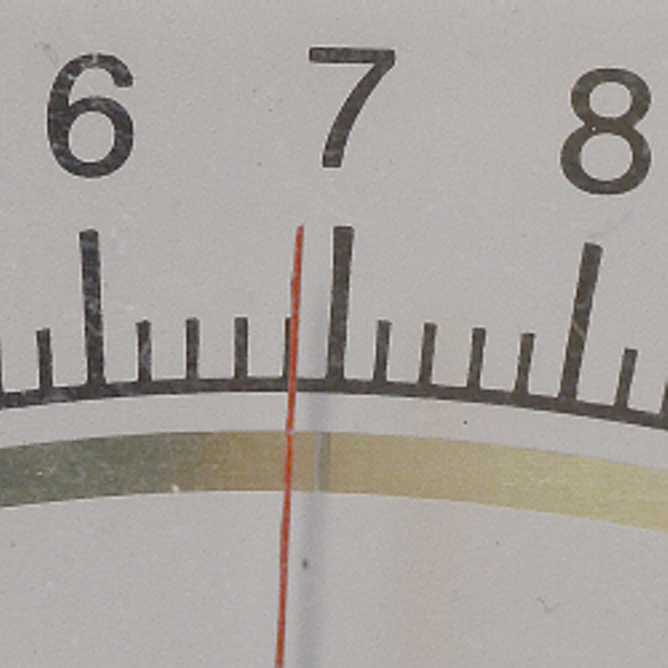 Parallax error on an analog meter. The needle's reflection, visible on the mirror below the scale, indicates that this is an improper viewing angle. Source: University of Cincinnati-Clemont.
- Multiple scales can cause confusion. (Scales are discussed in more detail below.)
- Analog meters lack auto-polarity technology. Incorrectly connected test leads can result in needle deflection and damage to the device.
- Parallax error, which occurs due to improper reading of analog measurement devices. Analog meters are designed to be read with the eye perpendicular to the needle and meter scale. When the scale is viewed at an improper angle, the meter's accuracy is compromised by several degrees. Some meters provide a mirror within the display, so that a user can easily determine the correct viewing angle by checking the needle's reflection. The proper angle is achieved when the needle's reflection is not visible to the user's eye.
Applications
Digital voltmeters have generally superseded analog types, but the latter still finds widespread use in niche applications such as:
- Battery indicators, especially in marine or naval craft
- Pulse or oscillation measurement, in which the movement of the indicator is more important than the precise voltage value
Scale and Range
Reading a voltmeter designed to measure only one voltage range is simple and straightforward, but many meters are configurable to measure multiple ranges and therefore employ more complicated scales. Many analog multimeters can measure both AC and DC voltages and can measure dozens of voltage ranges.
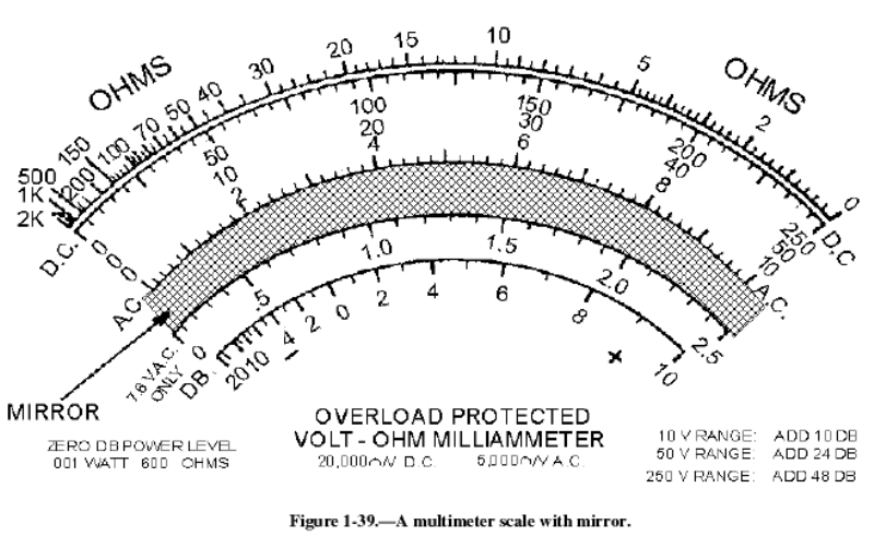 A multimeter scale with mirrorWhen viewing the scale above, a user may conclude that the meter is able to measure three different voltage ranges: 0-10V, 0-50V, and 0-250V. More typically, a meter with the above display can measure other ranges which are multiples of the three basic ranges, such as 0-0.5V, 0-2.5V, and 0-1000V.
The video below provides a helpful overview of calibrating and reading an analog multimeter (the section on reading voltage begins around 3:45). Click to watch video.
The multimeter selector switch shown below provides a good example; note that all DC voltage figures at left are multiples of 25, 50, and 100.
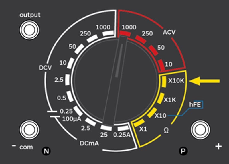 Multimeter selector switch. Image Credit: Electronics Area
A user must therefore know to use the correct display scale for a selected range and determine a reading's percentage of full scale to find a measured value. For example, a needle reading of 2 on the 0-10V scale is interpreted as 200V if the meter is configured to measure 0-1000V.
When measuring an unknown voltage, calibrating a meter to the highest range prevents it from "pegging" at full deflection (the needle moving rapidly to the top of the range) and mitigates damage to the meter. When measuring a known voltage, set the meter to the smallest range which can accommodate the voltage. For example, a 9V battery should be tested on 0-10V, while a 120V outlet should be measured on 0-250V.
Standards
Published standards related to voltmeters typically concern the device's use for electrical testing. Example standards include:
IEC 60051-2—Special requirements for analog ammeters and voltmeters and their accessories
ASTM A1013—Test method for high-frequency core loss of soft magnetic core components using the voltmeter-ammeter-wattmeter method