Temperature management in automotive bus bar systems
August 09, 2022 Figure 1. More and more automobiles are plugging in instead of filling up. Source: Herr Loeffler/Adobe
As electric vehicle (EV) technology continues to develop, more power to the wheels means more instantaneous current discharge from each individual battery cell. This current flows through a central bus bar in the battery unit, creating heat along the way. At the same time, more power, plus the need for increased range, means that battery capacity will ideally need to increase as well. To charge such high-capacity batteries in a reasonable amount of time therefore means that inbound current capacity must be increased, too.
On both the outbound (driving) and inbound (charging) conditions, bus bar systems must be designed and built to deal with a large amount of current, and the heat it generates. Isabellenhütte is an industry leader in optimizing this technology based on market challenges.
Bus bar current transmission challenges
While bus bars inside of an overall battery unit are designed to carry a large amount of current, they resist current flow to some extent, like all conductors. Components in battery disconnect units (BDUs) such as relays, measurement equipment and connectors are integrated into an EV’s overall battery assembly and add to this resistance. This impediment to current flow results in heat generation, sapping a vehicle’s energy that would ideally all be transferred to the wheels, to instead increase internal temperatures. It is necessary to bend bus bars in BDUs to account for tight space restrictions with every turn, creating a higher current density and thus additional internal resistance. Joints are another additional resistance source. While welded connections yield the best results, mechanical clamping via a bolted connection is often more practical and hence is more often employed. Mounting torque and the electrical resistance of the bolt have an influence over this so-called joint resistance, as do the relative properties of each attached surface. Roughness and any contamination, such as grease, can also contribute to electrical current resistance between surfaces.
In addition to the aforementioned factors, automotive battery systems (which contain an array of individual cells, bus bars, BDUs and potentially other ancillary equipment) are normally sealed off from the environment to prevent moisture ingress. This sealed environment also has the effect of locking in heat to a large extent, making temperature management in battery systems challenging. Temperature factors must be considered in charging stations as well but wouldn’t be subject to the same kind of space restrictions and variable loads present in the EVs themselves.
Bus bar heat management
 Figure 2. Temperature management in bus bar systems is critical both when driving and when charging. Source: unlimit3d/Adobe
To combat overheating, heat generation in bus bar systems should first be addressed by using conductors with a sufficient cross-section. Generally, it is best practice to follow a rule of thumb of 2 A/mm2 i.e., for every 2 A of anticipated current flow, there should be 1 mm2 of conductive surface through which current can flow. Conductors should also be made as straight as possible, and materials should be specified properly. Ideally, current resistance at the joints should be matched with optimal fasteners.
Once the inherent heat generation of a bus bar system has been minimized, component ratings then need to be considered. Battery system components are often rated from -40° C to 125° C, which can quickly be exceeded in normal automotive operation.
Temperature sensing for active heat management
Some battery system components, such as the Isabellenhütte Smart Sensor IVT-S, can interface with the car’s overall control system and send a notification if the temperature exceeds a certain set point or if there is a malfunction. With this signal, an automobile or other system can then take measures to counteract this condition; this could include engaging an active cooling device, throttling power output or even shutting down motor power in extreme cases. Note here that such onboard temperature sensors are most likely not directly measuring the temperature in the hottest location within the component, or hotspot. In order not to exceed the components rated maximum temperature, which can cause a component failure, this must be accounted for with a lower programmed critical set point.
Select and apply Isabellenhütte components for proper heat tolerance
When it comes to using Isabellenhütte bus bar components, internal resistance and the resulting temperature increase in a system must be considered. Also, a user must take into account temperature rating, placement and feedback capabilities. The fundamental equation for resistive heat dissipation is:
Power Dissipation (PD - Watts) = Internal Resistance (RI - Ohms) x Current2 (I2 - Amps).
Expanding on this concept for a particular application, consider the IVT-S smart sensor example below.
Isabellenhütte Smart Sensor IVT-S
The Isabellenhütte Smart Sensor IVT-S uses a shunt-based current measurement sensor with a 20 µOhm shunt resistor rated at 1000 A continuous current. As noted above, power dissipation is expressed by the formula: PD = RI x I2. Therefore, at its maximum rated current, this sensor will continuously discharge 20 Watts (.00002-ohm x (1000 A)2) of power as heat to the environment. This heat will be created in the hot spot of the shunt resistor, which is the resistive alloy. From there, heat will be transferred to the environment typically through surrounding materials with the highest temperature conductivity. In this case, that would be the shunt legs and the bus bar.
The challenge is now to determine the exact temperature in the hotspot and to conclude how close it comes to the maximum allowed temperature of the used components. This is called the critical inner temperature, which is 125° C in this example.
The resulting temperature difference between the hot spot of the module (T1) and a reference temperature (T0) can be described with the formula ∆T=T1-T0. T0 can be any selected sensing spot; in this example, it is the spot where the temperature sensor of IVT-S sits.
As the hot spot temperature T1 normally can’t be measured directly, it is usually being calculated using the relation between ∆T and the thermal resistance Rthi, with Rthi being a constant that has to be determined experimentally.
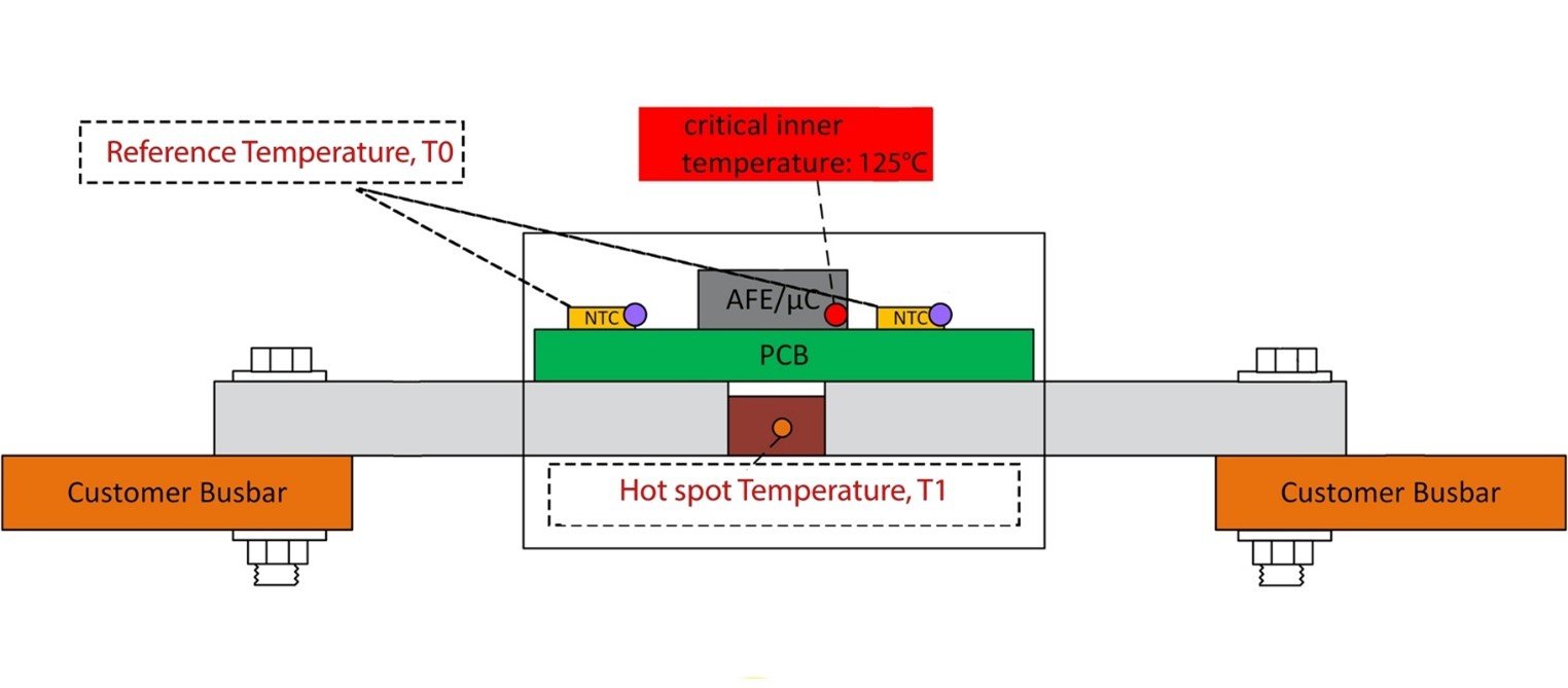 Figure 3. In BDU components, like the IVT-S Smart Sensor, the measured reference temperature and the temperature in the hotspot can differ significantly. Source: Isabellenhütte
The Smart Sensor IVT-S has an Rthi of roughly 1.0, considering the locations of T0 and T1.
With ∆T (T1-T0) = PD x Rthi and PD = 20W as determined above, ∆T can be calculated to around 20°K in this special case.
Hence, with T0 being the location of the internal temperature sensors, this will calculate the hot spot temperature T1 and estimate with high certainty how close it comes to the module’s critical inner temperature.
Isabellenhütte typically uses Ni-Ph plated copper legs in the smart sensor modules. However, if the underlying busbar material is not compatible with Ni-Ph, Isabellenhütte can offer custom solutions with pure copper or tin plating as needed.
Multiple component considerations
Isabellenhütte shunt resistors are rated up to 170° C, but components used in IVT-S Smart Sensors can only operate at up to 125° C. It should also be considered that different placement in battery or charging units can affect the ambient temperature. The Smart Sensor IVT-S has feedback capabilities to the battery management system main controller that can account for adverse conditions if action needs to be taken to lower the temperature.
Whether for a battery setup similar to what is presented above, or in any number of other implementations, standard concepts and calculations will need to be adapted to a particular situation. Isabellenhütte stands ready to adapt the advanced components to customer EV design challenges and can help spec or customize solutions as needed.
Isabellenhütte
Isabellenhütte Heusler is a Germany-based company with a longstanding history, reputation and expertise over three divisions: precision measurement technology, precision and power resistors and precision alloys. For more information on service offerings and part optimization, visit Isabellenhütte’s website.


