The guide to understanding driven wheel systems for material handling project designs
April 06, 2022Engineers create solutions to make manufacturing operations and processes more effective and efficient. These solutions need to meet exacting requirements, especially when a driven material handling solution is the answer. Driving or moving loads across a facility or moving a load with precise start and stop points requires consideration of many factors to make the solution as safe, effective and reliable as possible. This guide will highlight what components are needed and offer insight into the different factors that will determine the configuration of the driven wheel system for a project.
An overview of driven wheel systems
The successful design of the driven wheel system of a material handling project requires efficient and effective motion or movement. The requirements can change from very simple to much more complex. Engineers may need to find a system that will allow for precise starting and stopping points or a system to effectively handle very heavy or awkward loads.
 Figure 1: Every project has different goals and will have a different combination of AC motor, gearbox and wheel blocks. Source: Demag
Every material handling project has different requirements for a driven wheel system. Engineers may be designing a solution to transport heavy, awkward loads across a factory like a coil or transfer car. Finding a solution to meet the precise starting and stopping points for an indexer or palletizer machine has a very different set of requirements than the transport of a coil car. Moving a top-heavy load on a conveyor has an even different set of requirements when it comes to the drive system.
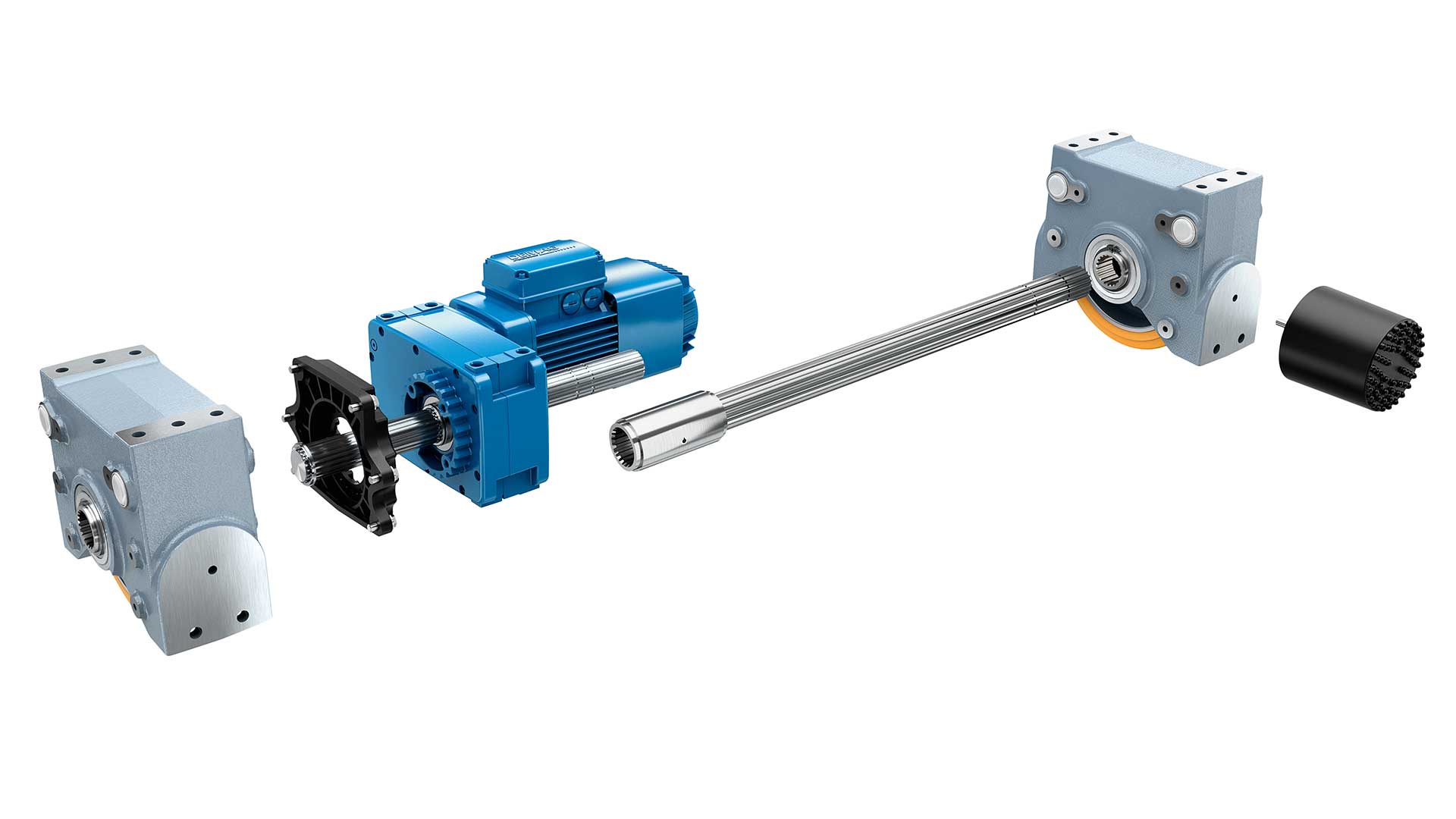 Figure 2: A complete driven wheel system includes the wheel blocks, electric AC brake motor, gearbox and connecting components. Source: Demag
A complete driven wheel system includes the wheels, electric AC induction brake motor, gearbox, electrification and connecting components to be added onto the carriage or machine. Purchasing all the driving components from one source makes diagnosing future issues with the drive system easier. All the engineering was completed by one source and it eliminates multiple contacts between multiple companies.
Continue reading to look at the factors necessary for the electric AC induction motor, gearbox and wheels to fit a project’s needs.
Powering motion-electric AC induction brake motors
A brake motor physically moves a load from place to place and allows the load to start and stop in its travel path. The specific motor used will match the cycle, duty, operating environment and other factors to move the load efficiently and effectively to the intended destination. When an application needs to stop at some point in the process, whether extremely accurately or not, look into AC induction brake motors for these applications. These motors have a brake integrated in or added on, so users have control over the stopping position.
- The AC motor used will be dependent on several factors including the number of cycles, duty factor needed, operating environment, power options and other factors. Looking at the needs of a project from the perspective of these factors, this is what they mean.
- The number of cycles is simply the number of times the motor will start and stop within a given timeframe, for instance, per hour. The more stops in the process, the greater number of cycles the motor must handle.
- Duty factor is directly related to the actual running time of the motor. The more time the motor runs, the higher the duty is considered so engineers need to make sure the motor can handle the requirements of the application.
- Operating environment is important because a specialized motor may be necessary for use in extreme environments like galvanizing shops, very hot areas and areas with a lot of moisture. The same motor used for an indexer in the automotive industry may not be the ideal AC motor that powers a crucible in a casting shop or furnace area.
- Since these motors are electromechanical, knowing the power requirement is vital. Looking at the U.S. and Canada, these markets primarily use 60 HZ, 460 V (U.S.) or 575 V (Canada), three-phase power in industrial environments. Other worldwide locations will have different power requirements.
Types of electric AC induction brake motors
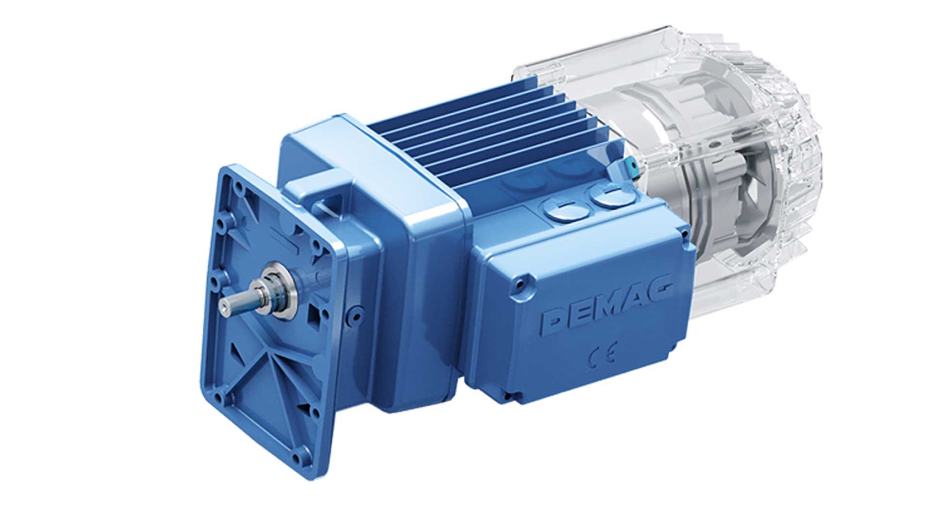 Figure 3: Cylindrical rotor motors have a brake attached and are generally for lower duty, lower cycle applications with inverter control. Source: Demag
There are a few different configurations of electric AC induction motors. First is a motor that is a cylindrical rotor with an attached brake. These are generally an option for lower duty, lower cycle applications and can be used with inverter control as a robust solution for everyday type service. Demag offers the Z-cylindrical rotor motor for these applications.
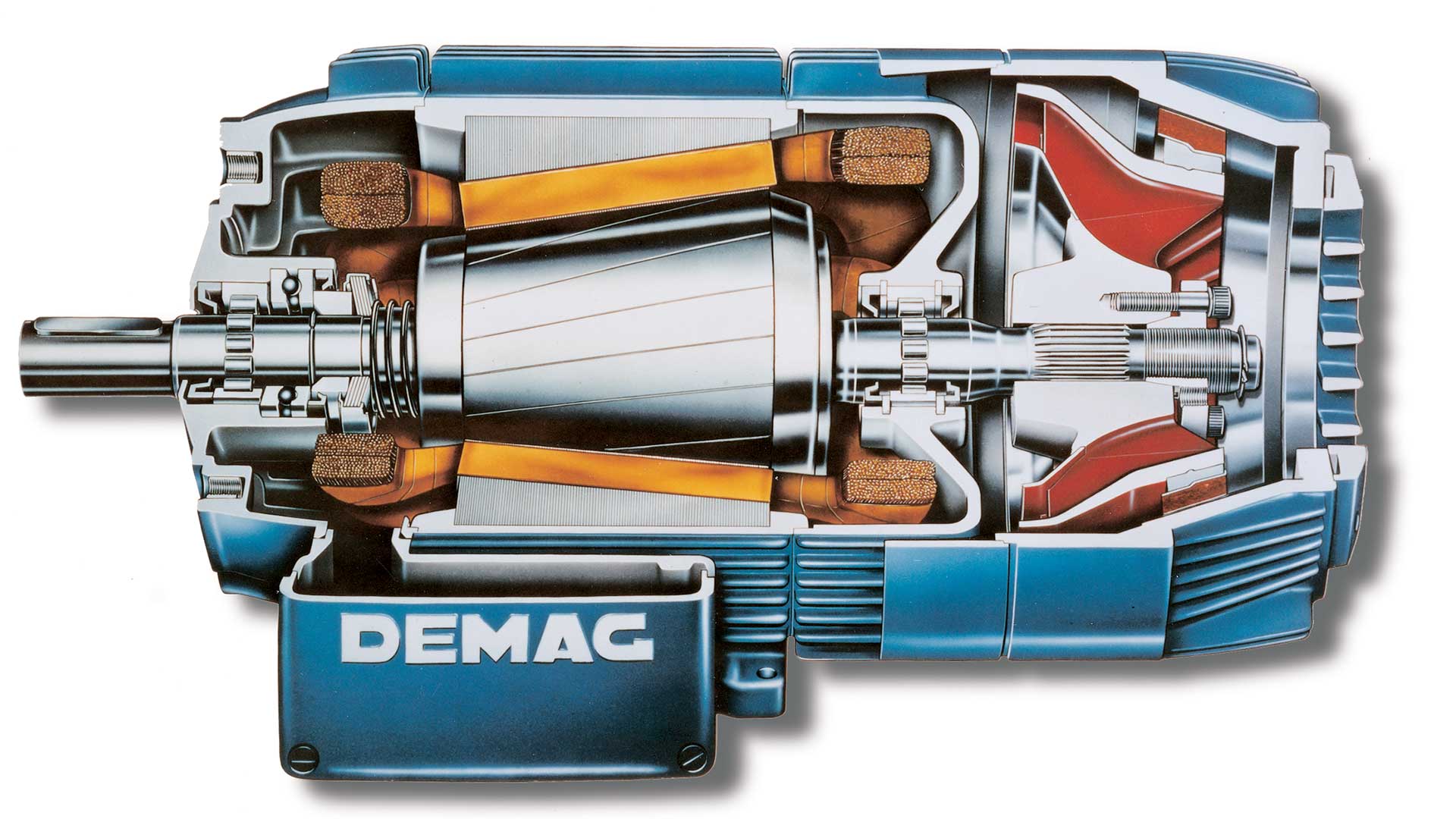 Figure 4: Conical rotor motors have a cone shape, which acts as a mechanical brake within the motor. Source: Demag
When requirements get more complex, a conical rotor motor can be used. These do not require additional electronic controls to actuate the braking motion, which is performed completely mechanically by turning the motor on and off. In addition, if the maintenance crew prefers to work on equipment using wrenches and tools, this option eliminates the complexity of programming or servicing inverters. These squirrel cage motors mechanically provide smooth acceleration and deceleration with an additional flywheel, thereby eliminating slippage wear to the wheel itself and the rail it runs on. Demag offers the reliable and tested KB conical rotor motor for these applications.
 Figure 5: The Demag FG Microspeed Combination is a unique combination that pairs a main motor and microspeed motor for a wide speed range and exacting position accuracy. Source: Demag
Some applications require even more specific requirements like specialized travel or very precise positioning. Demag offers a motor configuration of a squirrel cage motor, or conical rotor motor, set up with the FG Microspeed. This is a unique combination that consists of a main motor, microspeed motor and gearbox in between. The configuration allows for a wide mechanical difference in speeds from very fast to very slow.
With two motors to handle the load, a configuration like the FG Microspeed brings several benefits. First, this can lessen the wear and tear on each of the motors, from a service perspective. Second, the configuration has the potential for a 500-600:1 speed range, depending on application. This can give a wide selection of speeds for the necessary motions in processes, making handling both high speed and low speed motions efficient. Third, if one motor is out of service, the second can be used to fall back on. This may keep production moving despite the service need. Demag has chosen the FG Microspeed motor configuration for applications like automotive indexers, hoisting applications and palletizers.
Motion set to requirements — The gearbox
An important component of the power transmission system is the gearbox, which translates the motor speed into torque so the material handling solution is optimized to meet specific needs. In its simplest terms, the gearbox is the interface between the electric AC induction brake motor powering an application and the actual movement of the load at the wheels. It translates the RPM of the motor into the appropriate linear speed to drive the load.
 Figure 6: The gearbox, seen here in blue, connects the motor and wheel to translate the RPM of the motor into the appropriate linear speed for the wheel. Source: Demag
Torque: An overview
The forces put on gears inside the gearbox are torque, or rotational forces of motion. The gearbox increases torque in an application. Looking at an example of an application in design, the speed at the output of the gearbox is directly proportional to the gear ratio. This means if a 1750 RPM motor is attached to a gearbox with a 10:1 gear ratio, the output RPM at the gearbox will be 175 RPM. In this case, the gearbox increases the torque at the gearbox output shaft by a factor of 10.
Brake torque is another aspect to be aware of with precise starting and stopping points. It is multiplied by the gear ratio so it can deliver precise starting and stopping points without installing a larger motor brake.
Allowable input torque and rated output torque
When deciding to use an AC motor and gearbox, there are two types of torque applicable to a project. Allowable input torque is the total torque the gearbox shaft can take coming in from the motor. This is important to ensure the gearbox is sized properly to each application. Rated output torque is the torque generated by the motor multiplied by the gear ratio. This takes inefficiencies out to show the real torque rating.
Rated output torque is critical because this is what actually moves the load through the output shaft of the gearbox. It is also important when intermittent motion and precise start and stop points are required. Rated output torque is what gives the application enough torque to move and stop the load properly. Torque is really what does the work in these applications.
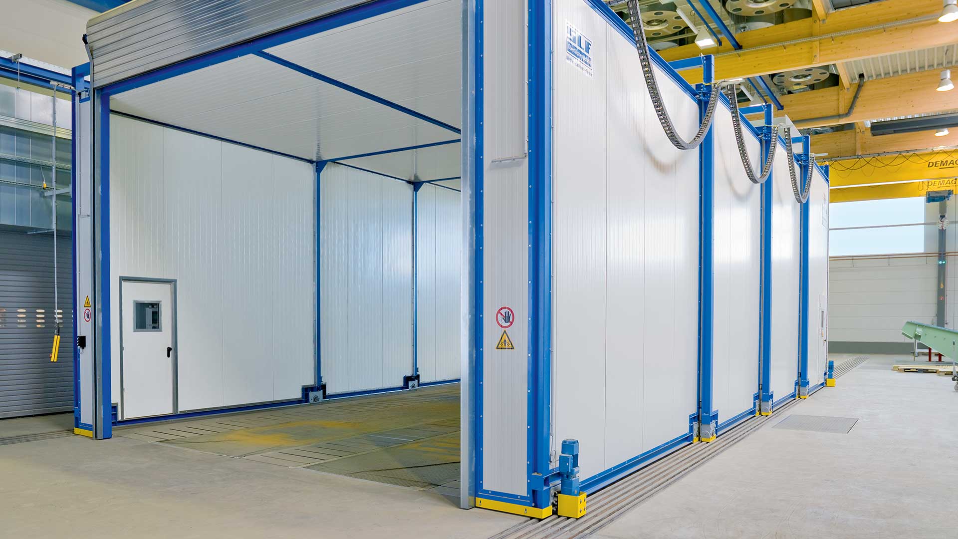 Figure 7: This paint booth is expandable to fit different sized components. The output torque of the gearbox is what moves the panels at the appropriate speed. Source: Demag
Horsepower versus torque
Horsepower and torque are proportionally related forces. In industrial applications, when using an AC motor and gearbox, the engineer would focus on horsepower. Horsepower describes the total motor performance of a drive system. In the world of automotive racing engines, horsepower is much more commonly heard of than torque because it is a gauge of the power of the entire engine system rather than the maximum gauge of one component. When using an AC induction motor, torque is the more important aspect because the output torque of the gearbox is what actually moves the load and determines how reactive and precise the application will be.
Gearbox efficiency
Efficiency is another aspect to keep in mind for choosing a gearbox for intermittent motion projects. Gearbox efficiency basically shows how much torque is lost as the motor speed is slowed or increased by the gearbox. Users may never reach 100% efficiency out of a gearbox, but it’s finding what works to meet the goals of an application.
Higher quality gearboxes allow the gears to deliver more precise motion and starting and stopping points due to the way the gears work within it. The ideal types for intermittent motion and precise start and stop points include helical, bevel and hypoidal style gearboxes. These style gearboxes are very efficient, typically 90% or higher, making torque precise and exacting.
Gearboxes are just one component of a driven wheel system in a material handling project. The gearbox is important because it creates the torque necessary for precise movement and for smooth starts and stops. Choosing a higher quality gearbox, like a helical style gearbox, can deliver high efficiency and high precision for an application. It can fit applications requiring precise starting and stopping points with intermittent motion.
Rolling motion — Wheels and wheel blocks
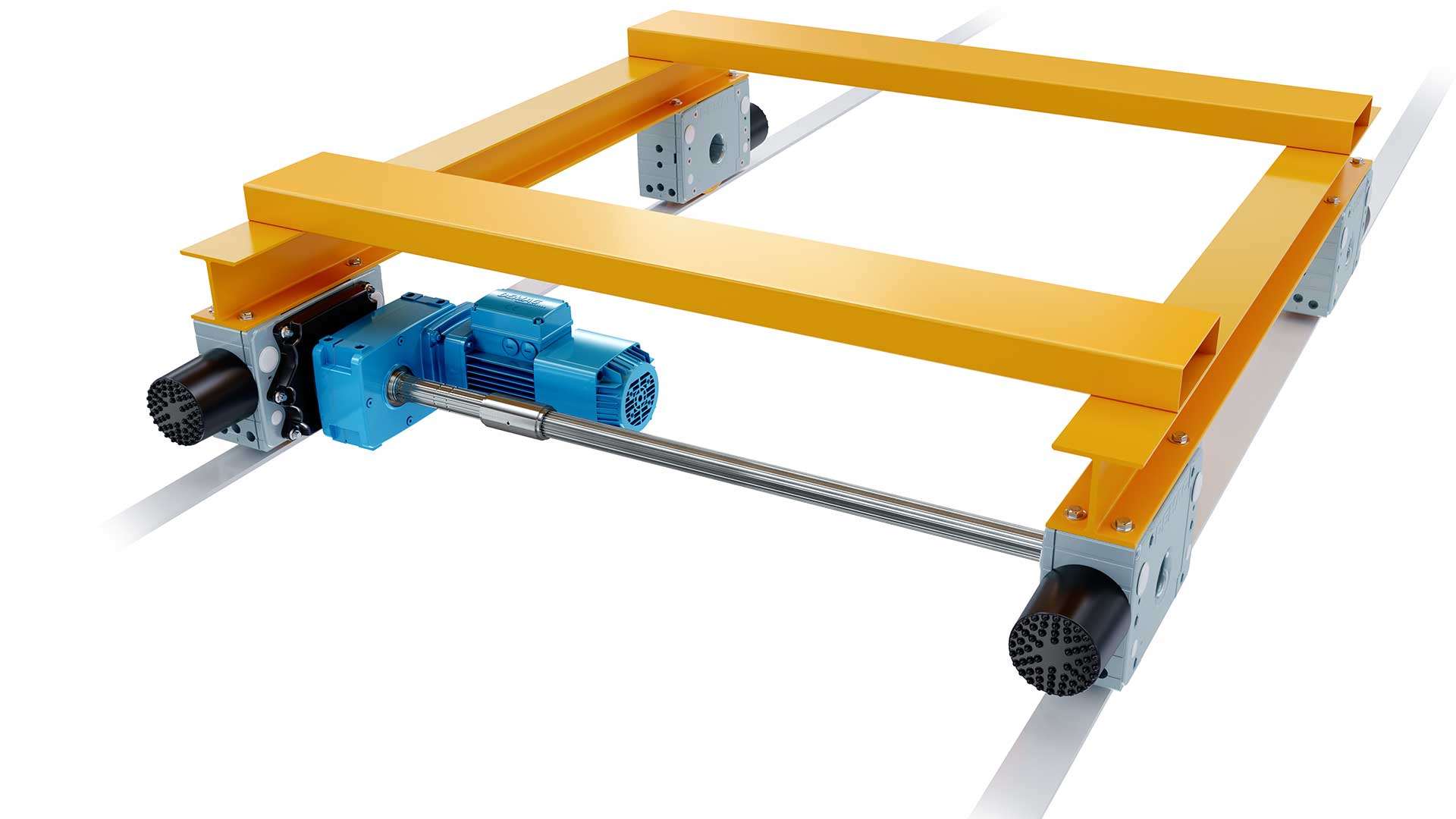 Figure 8: Drive system components connect together to create a solution like a transfer car, bolster car or coil car. Source: Demag
There are endless options for wheels to move a load. From simple to complex movements, there is an ideal type of wheel to use that can make material handling projects more effective. Powered wheels are typically used to move heavy loads on bolster cars, feeders, turn tables, crucibles, moving machinery and more.
Typically, wheels used for heavy loads or precise positioning are unidirectional, meaning they move along straight lines and curves but not in 360° motion like a caster. The wheels are also powered since the load is very heavy or the starting and stopping points need to be exact. These wheels are designed from materials that withstand the weight and environmental stresses put on them. There are many different materials and wheel designs to meet high capacity needs and extreme environments.
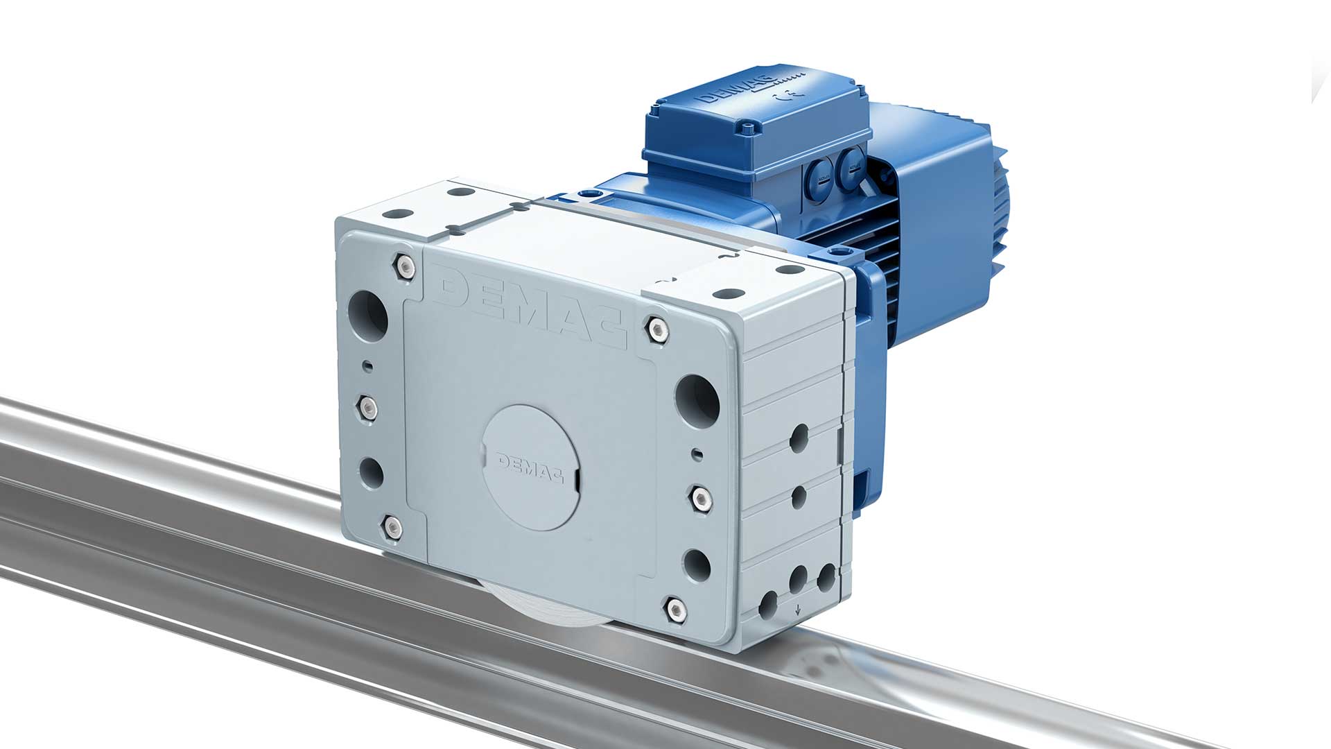 Figure 9: A wheel block contains the wheel, bearings, and support structure within the fixed housing so little engineering needs to be completed to add to a material handling project. Source: Demag
A wheel block is a unit that includes the wheel, bearings and support structure within a fixed housing. The “block” is simply the housing that contains all these components. Because the wheel block includes the bearings and support structure, there is limited engineering necessary. The engineering of the wheel block itself has already been completed so once the correct size is determined, the wheel blocks can be immediately installed. After all, wheels are just one part of the solution when a powered wheel system to position loads precisely or move heavy loads across a facility is needed.
A complete driven wheel system solution
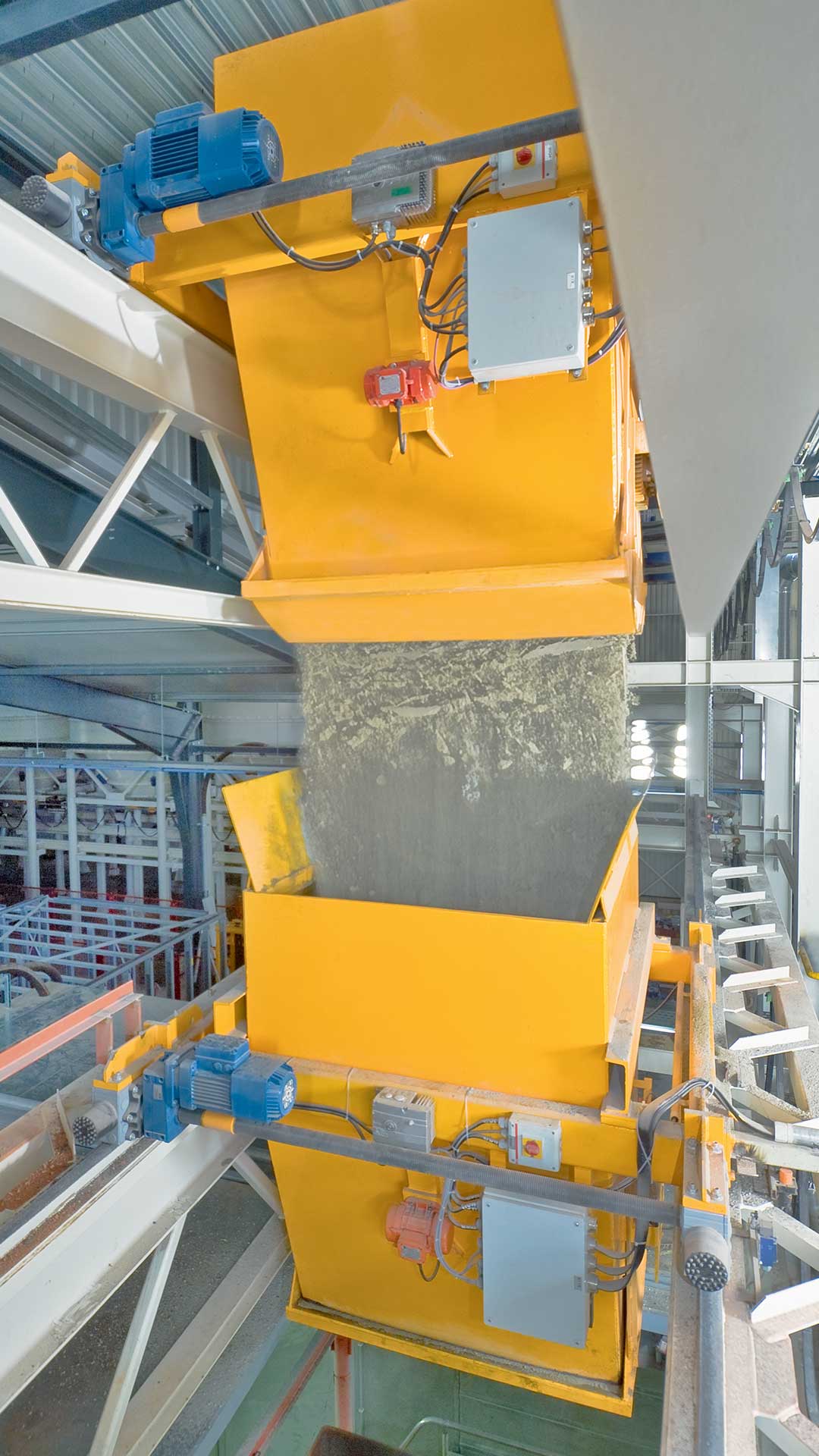 Figure 10: Working with one supplier to source a driven wheel system ensures the components are all engineered to work together. Source: DemagWhile gathering all the information needed to design a material handling project, it’s important to think about the future maintenance of the transfer car, indexer or feeder. The right solution for a manufacturing facility will be easy to maintain and create a reliable solution to complement and improve processes. When thinking about the driven wheel system, purchasing all the components from one manufacturer simplifies the future maintenance and repair processes. One company completed all the engineering of a project so it simplifies how to order parts for regular maintenance and potential future troubleshooting.
Demag is a manufacturer who can provide a complete solution to move heavy loads or loads with precise positioning needs throughout a facility. Demag’s components are modular so they are designed to work together seamlessly. Think of these in the sense of an erector set or tinker toys, where all the components fit together. Users can build almost anything.
Demag can engineer a complete driven wheel solution that includes the motor, gearbox, wheel blocks, electrification and connecting components. The wheel blocks are easy to maintain and replace. When sized correctly, they have at least a 10-year life, but in some applications, they last for decades. With a correctly sized motor and gearbox, a material handling project can provide ROI.
Contact the Drives design team to create a solution.