DC motor operation modes and speed regulation techniques
Ryan Clancy | March 09, 2021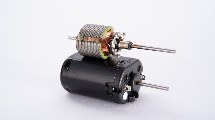 A DC motor with the outer casing removed, showing the interior components assembled as they would be when the motor is operational. Source: Meinhard/Adobe Stock
Direct current (DC) motors are typically found in electronic machines that require some sort of motion-producing or rotary control. These components are vital to the operation of various projects in the electrical engineering field. Design engineers must fully understand these different modes of motor operation and how to control their speed efficiently in order to create the best machine possible. This article will highlight the different DC motors available today, their various modes of operation and how to control their speed effectively.
What is a DC motor?
Alternating current (AC) motors and DC motors both create mechanical energy from electrical energy. DC motors operate in reverse compared to a DC generator, which creates electrical current, and runs on DC power — which is unidirectional and non-sinusoidal.
Construction
DC motors can be put together in multiple different ways, but all include the same foundational components:
- Commutator (for brushed or brushless motors)
- Field magnets (turns the axle attached to the rotor with a magnetic field)
- Rotor (also known as the “armature,” this is the rotating part of the machine)
- Stator (the part of the motor that is stationary, called the field windings)
In essence, DC motors work due to the relationship between the magnetic fields created by the rotating armature and the stationary part of the motor.
A DC motor with the outer casing removed, showing the interior components assembled as they would be when the motor is operational. Source: Meinhard/Adobe Stock
But, how do they work?
DC motors work by using Faraday’s principle of electromagnetism, which states: a conductor that carries a current will experience a force when located in a magnetic field. Fleming’s “left-hand rule for electric motors” states that the motion of a conductor in this position will always be in a perpendicular direction to the magnetic field and current.
The formula used to show this relationship is: F = BIL
- F = Force
- B = Magnetic field
- I = Current
- L = Length of conductor
Different types of DC motors
The many different types of DC motors can be segregated into a few categories, depending on how they are constructed. The main categories are brushed or brushless, parallel, permanent magnet, and series. The category that a DC motor falls into also determines its mode of operation, as can be seen in the below descriptions:
Brushed and brushless
Brushed DC motors use a couple of carbon or graphite brushes to deliver or conduct the current from the armature. They are generally kept close to the commutator in the motor’s construction. Other than delivering the current, the brushes control the direction of the current while rotating, keeping the commutator clean and ensuring sparkless operation.
A brushless DC motor, as the name suggests, does not use any graphite or carbon brushes. Instead, they 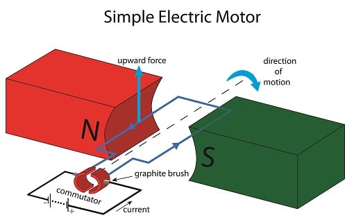 A diagram of a simple brushed electric motor, demonstrating how current moving through a motor creates rotation. Source: doethion/Adobe Stockutilize electronic circuits to maintain control of the speed and direction of the motor. These motors typically include a permanent magnet (or more than one) that rotates around the fixed armature.
Shunt
Shunt DC motors have their field windings and armature connected in parallel. This parallel connection results in both windings receiving the same voltage, even though they are separately excited. Generally, shunt motors have more turns on their windings than series motors, creating a more powerful magnetic field while the machine operates. This gives shunt DC motors exceptional speed regulation, even if the loads vary. They do lack the relatively high starting torque that series motors have because of their design.
Permanent magnet
Similar to a brushless DC motor, permanent magnet motors utilize two (or more) permanent magnets that oppose each other and surround the rotor. When DC is passed through, a magnetic field flux is generated, which rotates the rotor in either a clockwise or anti-clockwise direction, which depends on the polarity of the motor. This gives these motors the ability to operate at synchronous speed and hold a constant frequency, and this allows for ideal speed regulation.
Series-wound
A series motor has their copper field windings and (typically copper bar) stator windings connected in series. This results in the field currents and armature current being equal. High current is directly supplied into the field windings, which are fewer in number and thicker than those in shunt motors. This thickness raises the load-carrying capacity of the motor and allows it to create magnetic fields powerful enough to facilitate high torque.
DC motor speed control
DC motors can be controlled in three different ways: armature resistance control, flux control and voltage control.
Armature resistance
Armature resistance control is derived from the principle that states the back electric and magnetic fields (EMF) is directly proportional to the motor speed. Therefore, if the armature resistance and supply voltage are kept constant, the armature current is directly proportional to the motor speed. The greater the resistance in series with the armature, the more the speed decreases.
Flux
A rheostat (type of variable resistor) is used in flux control to increase the resistance in the field windings, which reduces the flux. This component is connected in series with the windings, and through increasing their resistance, the motor’s speed is increased. This puts a limit to maximum speed as the field flux can weaken past a certain limit, and this will adversely affect the commutation.
Voltage regulation
Shunt DC motors typically utilize the voltage regulation method. There are two different ways to accomplish voltage regulation control:
1. Multiple voltage control, which consists of connecting the shunt field to a fixed exciting voltage while changing the armature voltage. The voltage across the armature is changed with a switchgear, and the speed is approximately proportional to the armature voltage.
2. Ward Leonard method, where the voltage supplied to the armature is varied, and very sensitive and smooth speed control is required (for instance, elevators, electric excavators)
Why is it important to control the speed of a DC motor?
Controlling the speed of a DC motor is basically controlling the speed of the machine itself, as in a drill. The ability to increase and decrease the speed of the drill is essential as different materials have their own resistances, so speed control has a big impact on the performance of the drill. Speed control can either be taken care of manually by the worker, or it can be automatically controlled by the tool or a computer.
So, what do you think is the best type of DC motor and method of controlling its speed? Let us know in the comments below!