What’s inside a CubeSat?
Eric Olson | June 18, 2019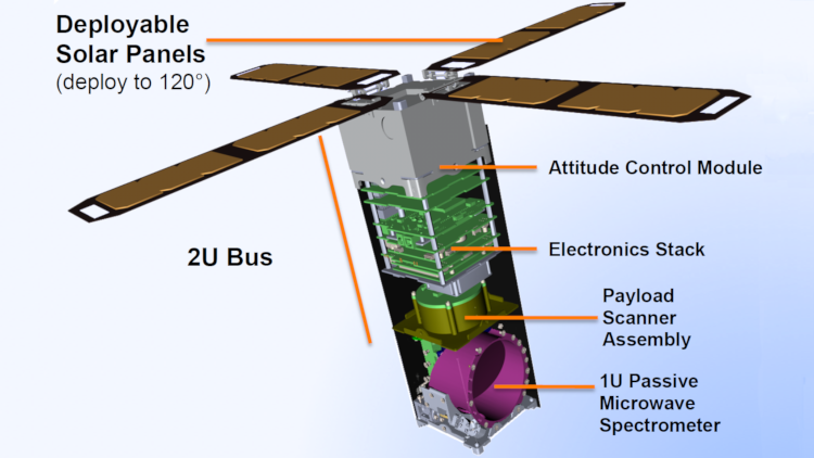 The MicroMAS-1 CubeSat consists of a 2U bus module attached to a spinning 1U payload module. Source: MIT
CubeSats are miniature satellites comprised of one or more cubic units about the size of a small tissue box weighing less than 1.33 kg. CubeSats are smaller, lighter and less power hungry than traditional large satellites. They are also faster and cheaper to develop, making them ideal platforms for technology demonstrations, scientific research and educational projects.
[For a step-by-step guide to CubeSat development, see How to develop a CubeSat: From concept to Earth orbit.]
 MicroMAS-1, a 3U CubeSat weighing 4.2 kg with dimensions of 32 cm x 10 cm x 10 cm. Source: MIT Lincoln Laboratory. (Click image to enlarge)
CubeSats, like all spacecraft, are comprised of a payload and several subsystems. The payload performs the primary objective of the mission (e.g., Earth imaging), supported by the subsystems that include the mechanical structure, thermal control, command and data handling, telecommunications, electrical power and attitude determination and control systems.
CubeSats fit a lot of functionality into a small form factor. This has been enabled by continual miniaturization of technology, including electronics, sensors and actuators. CubeSats share many of the same subsystems as larger satellites, just with reduced dimensions.
To find out what makes a CubeSat tick, take a look under the hood of MicroMAS-1, a CubeSat developed by MIT and launched in 2014. MicroMAS-1 was designed to demonstrate the potential of low-cost CubeSats to provide high-resolution, millimeter-wave radiometric images of severe weather events like hurricanes.
MicroMAS-1
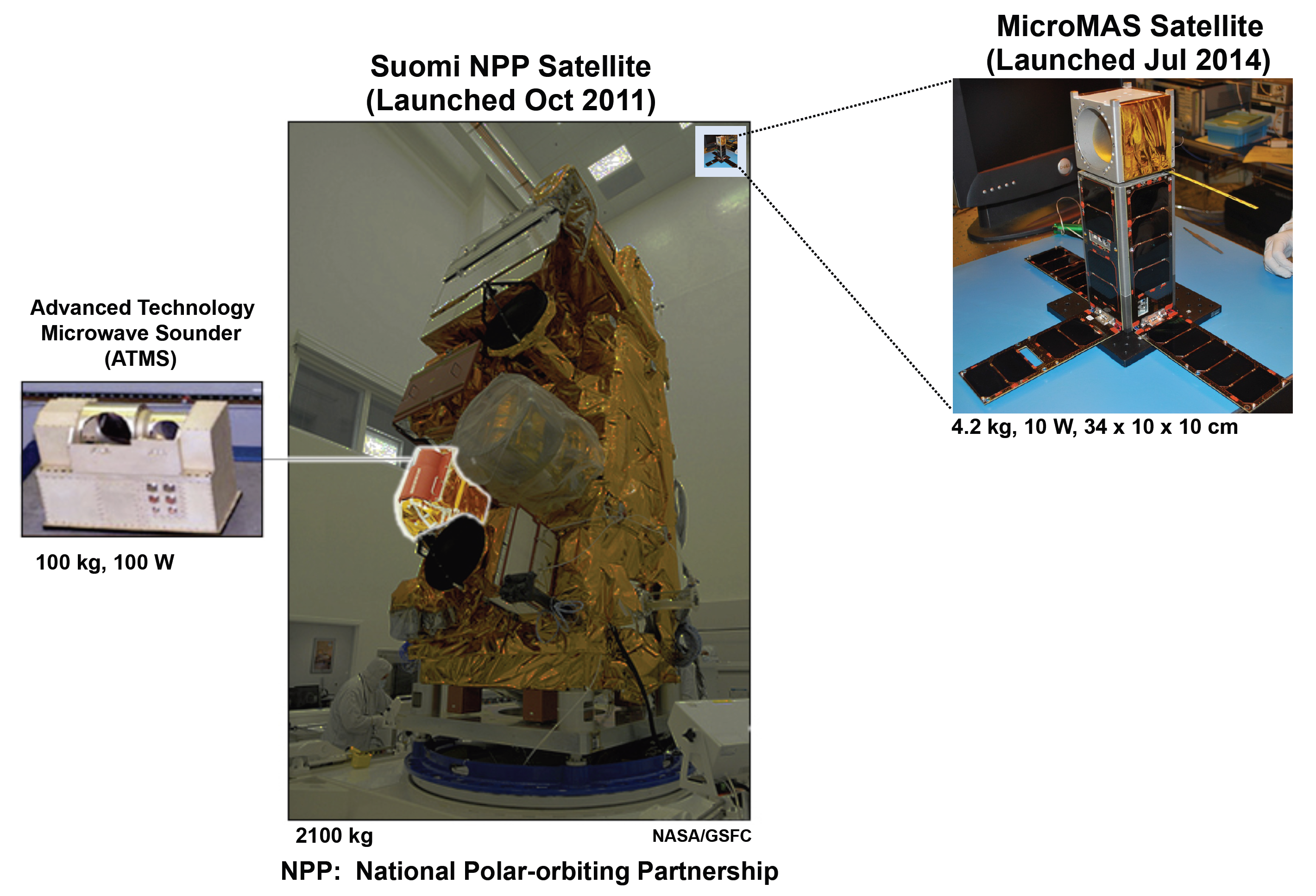 Size comparison of the National Polar-orbiting Partnership (NPP) satellite and MicroMAS-1. Source: MIT Lincoln Laboratory/NASA/GSFC. (Click image to enlarge)
The MicroMAS-1 CubeSat is a fraction of the size of traditional satellites. The size disparity is evident in this image displaying the National Polar-orbiting Partnership (NPP) satellite and MicroMAS-1. The Advanced Technology Microwave Sounder (ATMS) instrument mounted on NPP, which was launched in 2011, performs essentially the same functions as the scanning radiometer on MicroMAS-1. But ATMS alone is significantly larger than the entire MicroMAS-1 satellite.
To fit inside the NanoRacks CubeSat Deployer for launch, MicroMAS-1 had its solar panels and monopole tape-spring antenna folded up. Once deployed, the solar panels fold out to a 120° angle. Solar cells are mounted on the body of the CubeSat as well as both sides of each solar panel. Average power output is about 10 W.
Bus design
 The MicroMAS-1 bus stack. Source: MIT/27th Annual AIAA/USU Conference on Small Satellites. (Click image to enlarge)The CubeSat consists of a bus module attached to a spinning payload module. The chassis structure of the bus module is made of anodized aluminum and holds a board stack containing avionics. The bus module connects to an attitude determination and control system (ADCS) at one end of the bus and the payload at the other end.
The payload module contains a microwave radiometer that performs the main science mission, which is to collect millimeter-wave radiometric images of storms. The entire module continuously spins to allow the radiometer to be calibrated with measurements from deep space on each rotation. The spin also allows the sensor to observe a much wider area.
MicroMAS-1’s avionics stack is based on the standard CubeSat Kit (CSK) design by Pumpkin Inc., which consists of a stack of connectorized boards with standard pin mappings. Two custom interface boards are integrated with this stack to provide electronics specific to the mission.
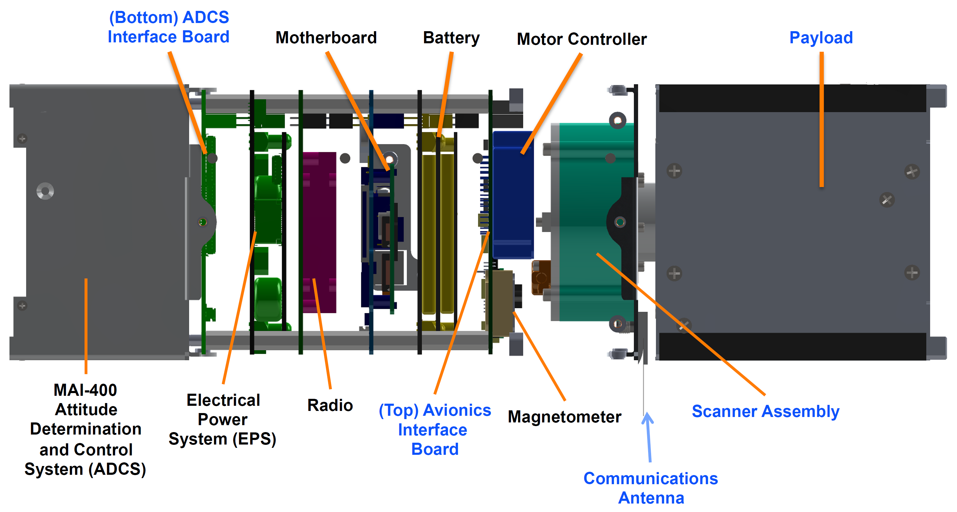 MicroMAS-1 bus design. Source: MIT Lincoln Laboratory. (Click image to enlarge)
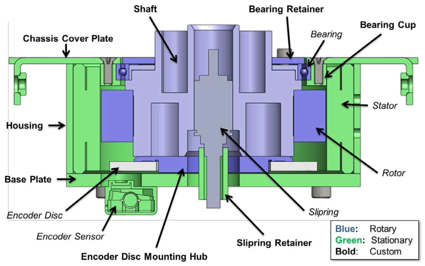 Cross-section view of MicroMAS-1’s scanning assembly. Commercial-off-the-shelf products are shown in normal typeface and custom-made parts are in bold. Source: MIT (Click image to enlarge)
The scanner assembly just beneath the payload module enables rotation of the payload. The scanner assembly contains an Aeroflex Z-0250-050-3-104 brushless DC zero-cogging motor controlled by an Elmo Hornet motor controller. Position feedback is provided by a MicroE M1500V optical encoder and MicroE 301-00075 rotary grating. An NHBB deep groove, thin-section radial ball bearing was chosen due to size constraints for a single bearing that did not require a duplex mounting configuration. A 12-wire slip ring module (Aeroflex CAY-1398) connects the bus and payload modules, allowing power and data transfer between the stationary and rotating sections of the CubeSat.
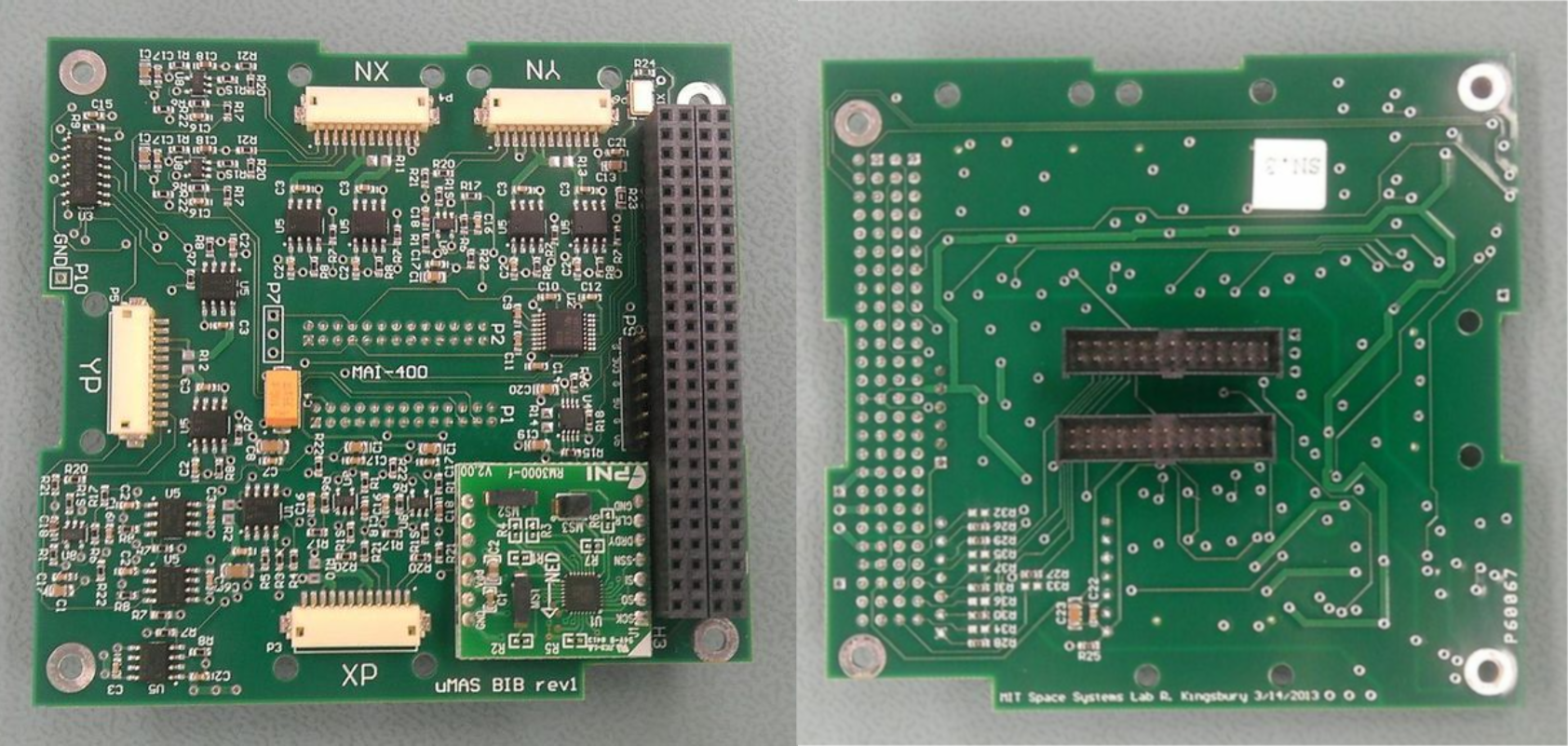
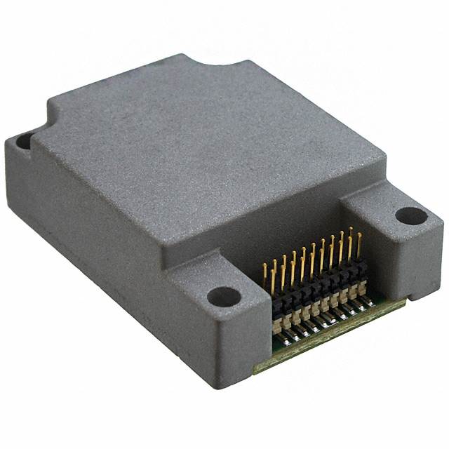 The ADIS16334 inertial measurement unit. Source: Digi-Key Electronics. (Click image to enlarge)The top interface board is located just below the scanner assembly and contains the motor controller and several other components. A magnetometer (PNI RM3000) and inertial measurement unit (IMU) with three-axis gyro (ADIS16334) provides data for the ADCS to orient the spacecraft. Temperature sensor interface circuitry connects to Innovative Sensor Technology’s resistance temperature detectors (P1K0) to provide on-board temperature monitoring.
Thermal management of MicroMAS-1 is mostly passive, although some parts require active heating to keep them above their minimum operating temperatures, including the batteries and MicroE encoder sensor. The top interface board also contains several power distribution units (PDUs), consisting of high-side power switches that enable the on-board computer to manage power received by the CubeSat’s subsystems. The board also has an RS-422 interface that transports data between the payload and bus.
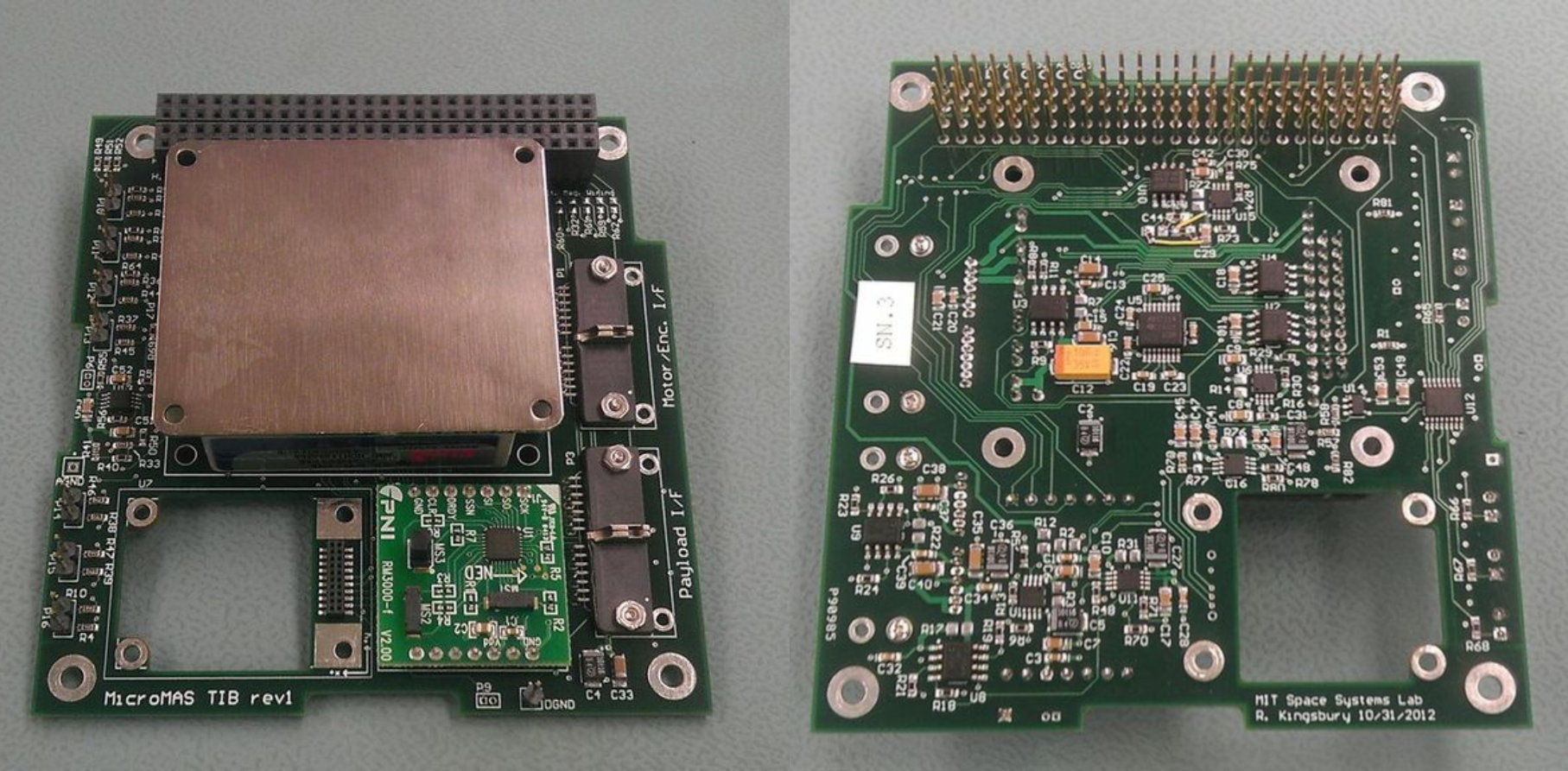 MicroMAS-1 top interface board top (left) and bottom (right). Source: MIT. (Click image to enlarge)
The motherboard, located below the battery, contains the on-board computer. MicroMAS-1’s Pumpkin CubeSat motherboard contains a PIC24F microcontroller.
The radio communications board, located below the motherboard, contains an L-3 Cadet UHF nanosatellite radio for which a custom carrier card was created to link its inputs and outputs to the correct pins on the bus. The board also contains PDUs to control power to the radio, as well as 4 GB of memory that serves as a buffer to store data for when the CubeSat’s is out of range with NASA’s Wallops Flight Facility. The radio connects to a monopole tape spring antenna, which is stowed beneath the solar panels before deployment.
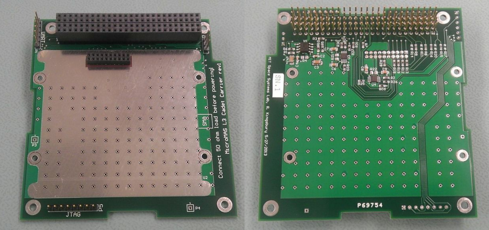 MicroMAS-1 radio carrier board top (left) and bottom (right). Source: MIT. (Click image to enlarge)
The electrical power system (EPS), located below the communications board, consists of a ClydeSpace EPS (CS-XUEPS2-60) which manages onboard power. The EPS gathers electricity generated by the solar panels, charges the lithium polymer batteries and distributes power on 3.3 V, 5 V, 12 V and raw battery voltage lines.
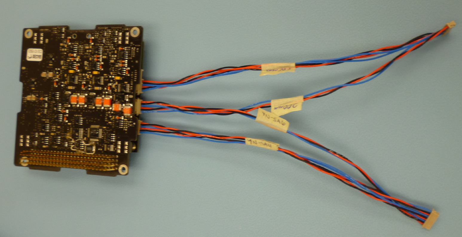 MicroMAS-1 ClydeSpace electrical power system. Source: MIT (Click image to enlarge)
The bottom interface board is located just above the ADCS to which it is connected with a rigid board-to-board interface connector. The bottom board contains PDUs that supply power to the ADCS, as well as an interface that transfers data to the ADCS from sun sensors (Silonex SLCD-61N8 photodiodes) that are mounted on the outside of the CubeSat.
 MicroMAS-1 bottom interface board top (left) and bottom (right). Source: MIT (Click image to enlarge)
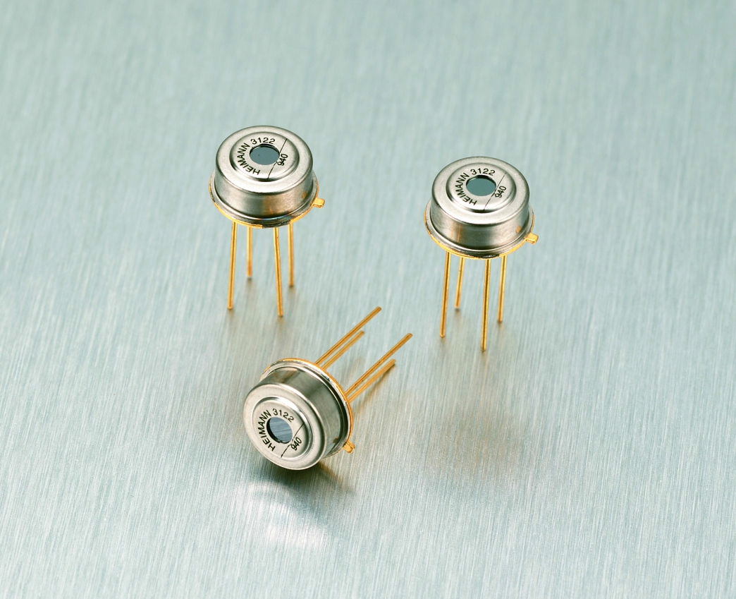 Excelitas TPS 334 Thermopile sensor. Source: Excelitas (Click image to enlarge)
The ADCS, located at the base of the CubeSat, controls the orientation of MicroMAS-1, cancelling momentum generated by the spinning payload and maintaining orbit stability. It accomplishes this by using sensors and actuators. The ADCS computes orientation based on sensor data from the magnetometer, IMU, sun sensors and Earth horizon sensors (Excelitas TPS 334 fine and coarse thermopiles). Based on this information, the ADCS operates three reaction wheels (MAI-400) along with torque rods that shed momentum magnetically.
 The MAI-400 1/2U CubeSat ADCS (left) and Static Earth Sensor mounted inside the MAI-400 (right). Source: Maryland Aerospace Inc. (Click image to enlarge)
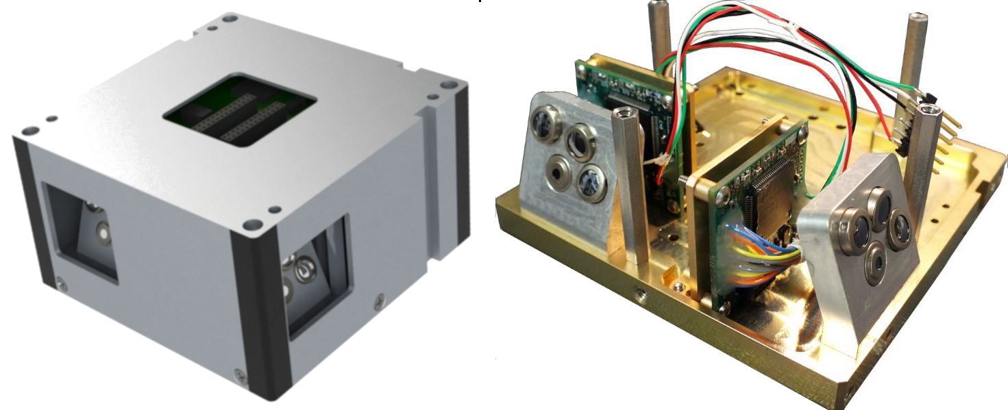
The scanning radiometer payload onboard MicroMAS-1, a 118 GHz spectrometer, measures 10 cm per side, weighs less than 1 kg and consumes less than 2 W of power. Compared to state-of-the-art equipment that existed prior to MicroMAS-1, the CubeSat’s spectrometer shrinks size, weight and power consumption by a factor of 100.
 MicroMAS-1’s payload, a passive microwave spectrometer/scanning radiometer. Source: Massachusetts Institute of Technology Lincoln Laboratory (Click image to enlarge)
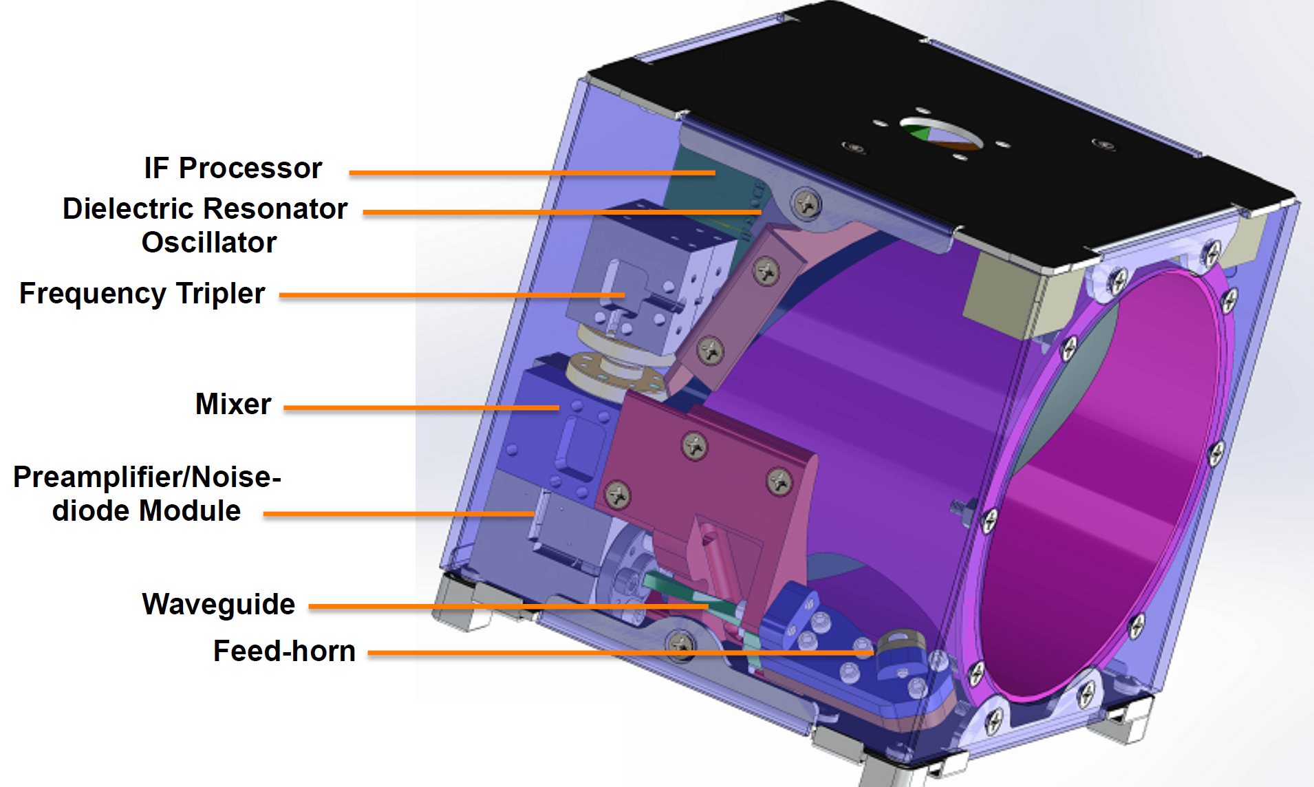
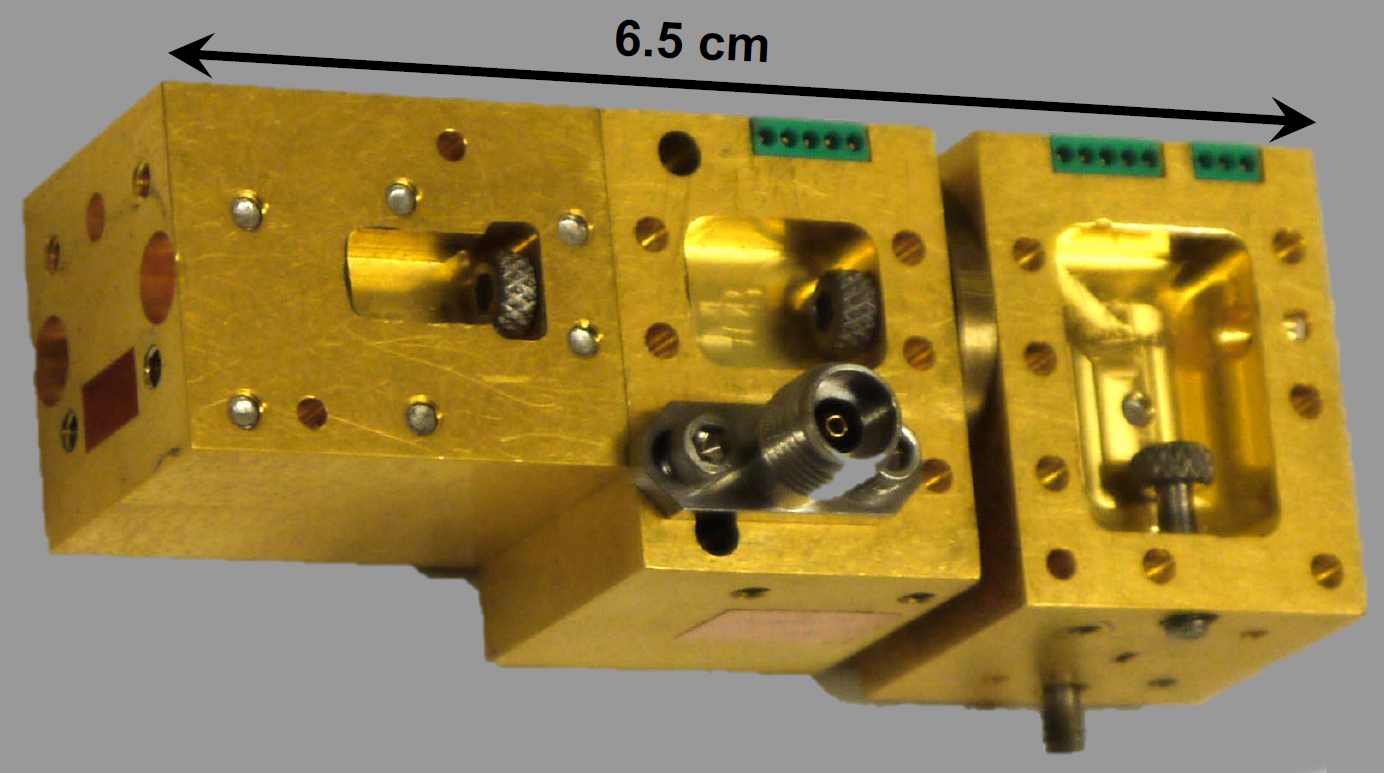 MicroMAS-1 microwave receiver front end. Source: MIT (Click image to enlarge)
The radiometer contains an offset parabolic reflector antenna that focuses incoming RF energy onto a feed horn integrated with a waveguide assembly that feeds RF front-end electronics. The superheterodyne receiver front-end contains an RF preamplifier, which consists of an RF amplifier and a weakly coupled noise diode for calibration; a mixer module containing a high-electron mobility transistor diode mixer and an intermediate frequency preamplifier monolithic microwave integrated circuit; and a local oscillator, which uses a dielectric resonator oscillator and a resistive diode tripler.
MicroMAS-1 also contains an intermediate frequency processor (IFP). The IFP processes incoming RF energy, performing channelization, detection and analog-to-digital conversion. It contains operational amplifier chips, active filter chips, ADC converter chips and a microcontroller.
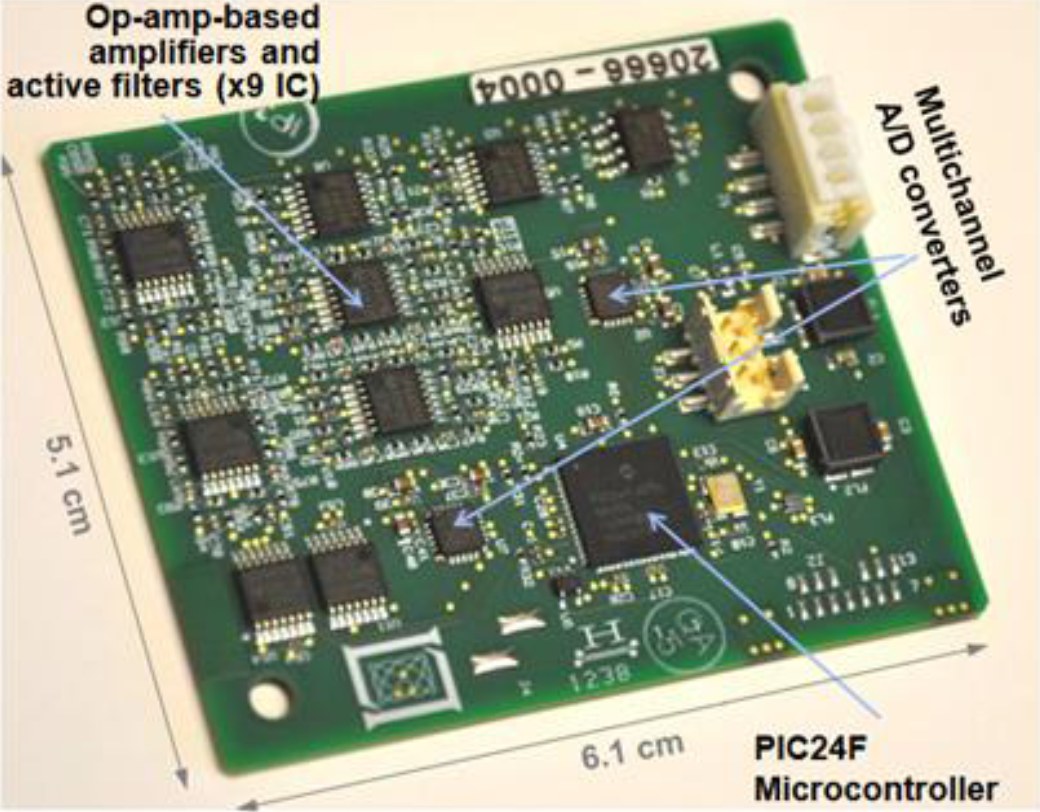 MicroMAS-1’s intermediate frequency processor. Source: MIT/28th Annual AIAA/USU Conference on Small Satellites (Click image to enlarge)
Block diagrams
 Block diagram of MicroMAS-1 showing the major components of the CubeSat’s subsystems and the data and power links between them. Source: MIT (Click image to enlarge)
MicroMAS-1’s components are a mix of commercial-off-the-shelf (COTS) products and custom parts. CubeSat designers attempt to maximize usage of COTS products to save time and money compared to custom-made components.
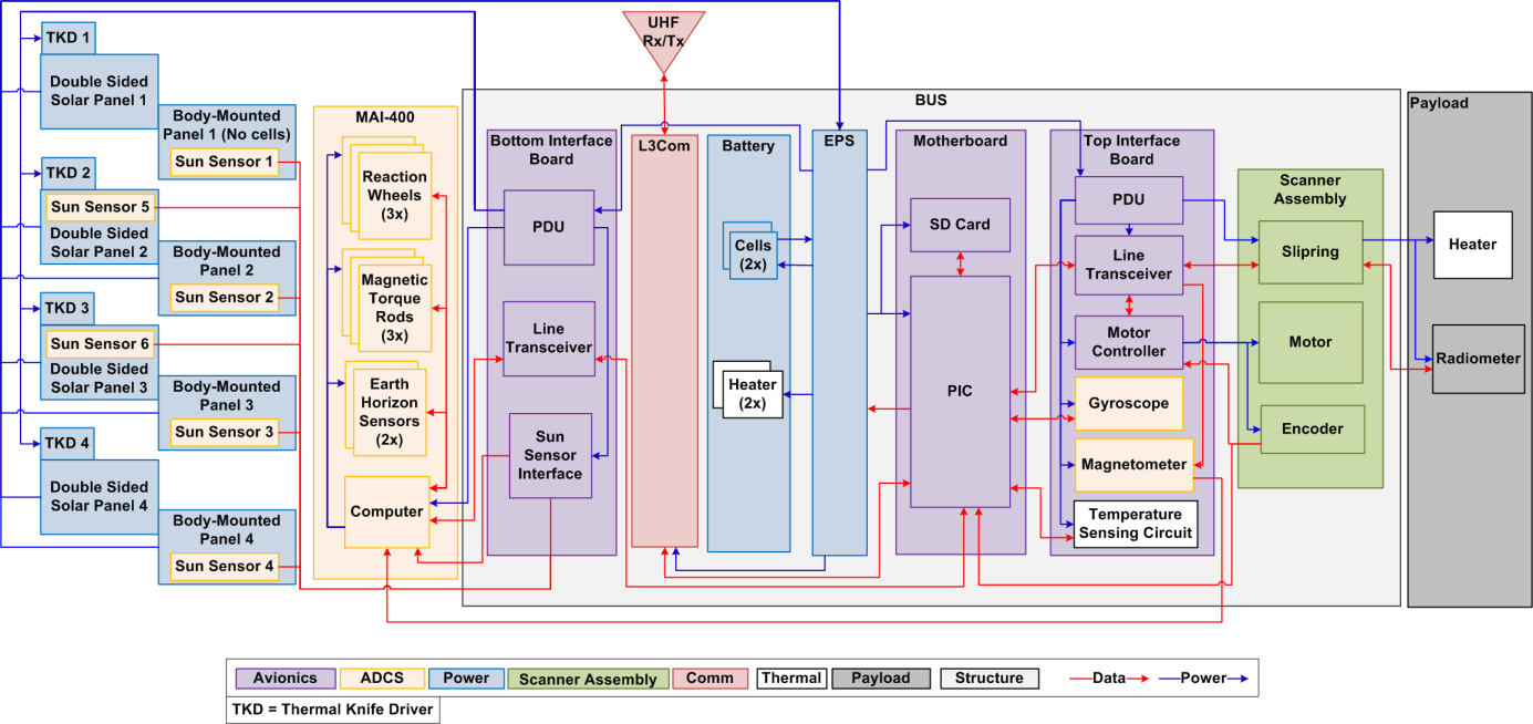
 Functional block diagram of MicroMAS-1 showing commercial-off-the-shelf components (in blue) and custom-made components (in red). Source: MicroMAS Team via ESA’s eoPortal (Click image to enlarge)
Background
MicroMAS-1 was developed by MIT’s Lincoln Laboratory and Space Systems Laboratory in collaboration with the University of Massachusetts at Amherst. The CubeSat was the first in a line of microwave sounding CubeSats that are paving the way to low-cost, high-resolution weather observation satellites.
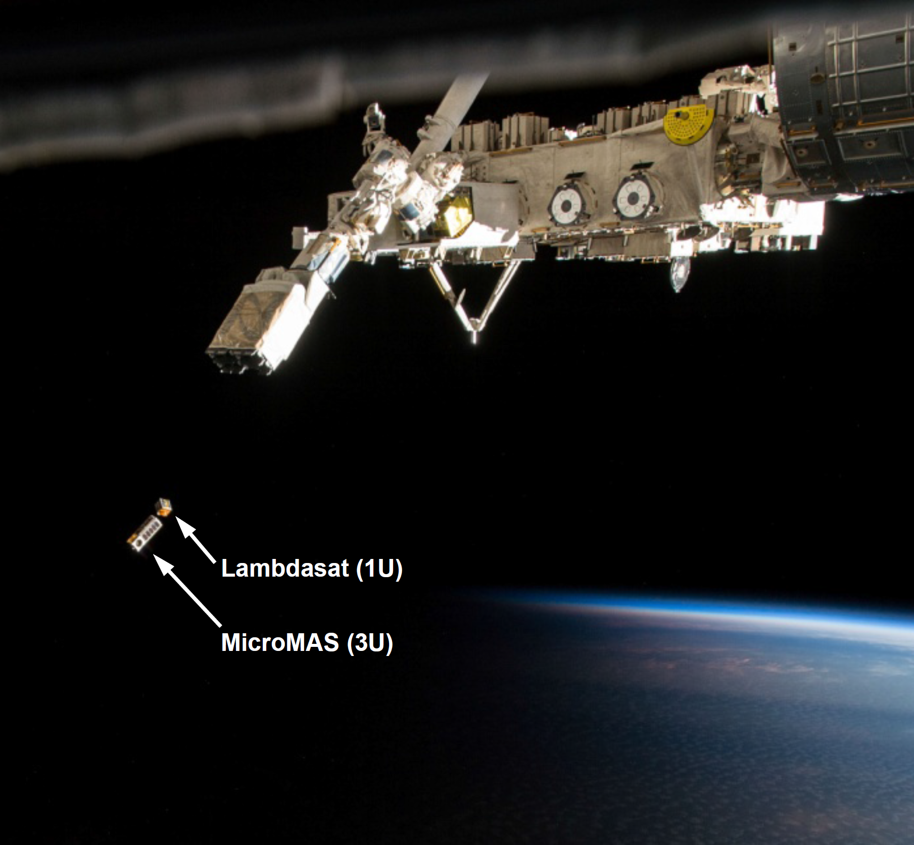 The MicroMAS-1 CubeSat just after being deployed from the NanoRacks CubeSat Deployer on the International Space Station on March 4, 2015. Also pictured is LambdaSat-1, a separate CubeSat deployed at the same time as MicroMAS-1. Source: Nanoracks/NASA (Click image to enlarge)MicroMAS-1 launched on July 14, 2014, aboard an Antares-120 rocket and deployed from the International Space Station’s Japanese airlock on March 4, 2015. Although the CubeSat experienced a transmitter fault two weeks into the mission, and no payload data was able to be downloaded, MicroMAS-1 served as an important step in the development of microwave sounding CubeSat technology.
Follow-on missions included the Microwave Radiometer Technology Acceleration project, launched on November 14, 2017, aboard a Delta II rocket, which experienced failure of its primary and backup radios and never returned data.
Success was finally realized with MicroMAS-2A, launched on January 12, 2018, aboard India’s Polar Satellite Launch Vehicle. MicroMAS-2A demonstrated microwave sounding data from a CubeSat for the first time, returning data on temperature, water vapor, cloud parameters and precipitation. An improved version, MicroMas-2B, is set to launch on Virgin Orbit’s LauncherOne in 2019.
The technology developed in the MicroMAS program will be put to use for the Time-Resolved Observations of Precipitation Structure and Storm Intensity with a Constellation of Smallsats (TROPICS) mission. TROPICS will consist of a constellation of CubeSats performing radiometer scans of Earth’s atmosphere to deliver high-resolution measurements of key environmental parameters needed to study weather events. It is expected to launch in 2020 at the earliest.
 The TROPICS mission will consist of a constellation of microwave sounding CubeSats. Source: NASA (Click image to enlarge)
Resources
Marinan, Anne and Cahoy, Kerri. “From CubeSats to Constellations: Systems Design and Performance Analysis.” (2013).
Blackwell, William, et al. "MicroMAS: A first step towards a nanosatellite constellation for global storm observation." (2013).
MicroMAS-1 | eoPortal